Environmentally sealed cable breakout assemblies
a technology of environment sealing and cable breakout, which is applied in the direction of cables, insulated conductors, instruments, etc., can solve the problems of large number of cables, unfavorable tower space occupation, and the loss of signal and power consumption
- Summary
- Abstract
- Description
- Claims
- Application Information
AI Technical Summary
Benefits of technology
Problems solved by technology
Method used
Image
Examples
first embodiment
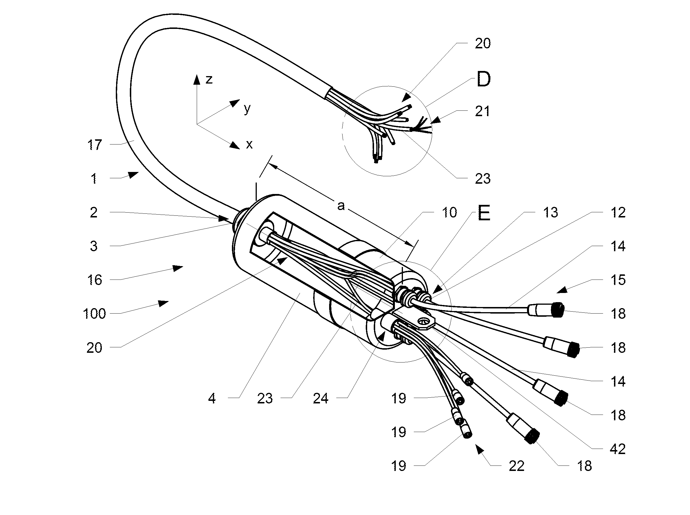
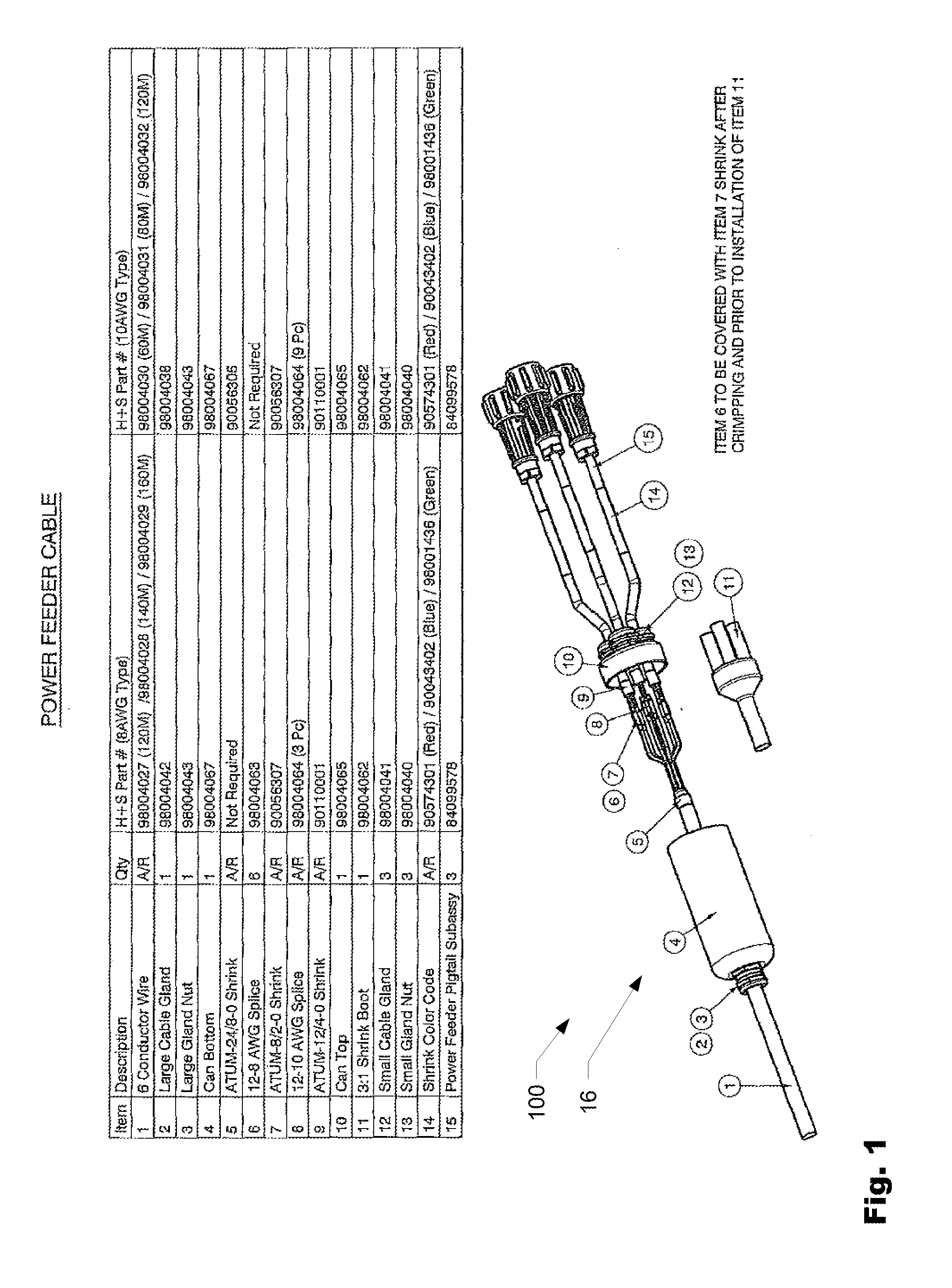
[0040]FIG. 1 is an exploded, perspective assembly view of a cable breakout assembly 100 according to the present invention. The cable breakout assembly 100 includes a feeder conductor wire 1, which is fed through a large cable gland 2 of a large cable nut 3 extending from the closed end of the bottom portion 4 of the breakout enclosure (can) 16. The conductor feeder cable 1 is spliced, crimped with respective radio leads and sealed with shrink tubes, as denoted by numerals 5-9. A shrink boot 11 is fitted over the sealed splice / crimp area denoted by reference numbers 5-9. The crimped, sealed, radio lead sections are fed though three cable glands 12 of respective cable nuts 13 which extend from the closed end of the top portion 10 of the breakout enclosure (can). The respective radio leads are shrink sealed and color coded (as shown by reference numeral 14) and interface with the power feeder pigtail subassembly at reference numeral 15, which are fitted with respective connector devic...
second embodiment
[0044]FIG. 6 is a schematic side view of a cable breakout assembly referred to as a splice puck 200 according to the present invention, and FIGS. 7A and 7B are cross-sectional views of the splice puck breakout assembly shown in FIG. 6. Suitable examples of materials for the splice puck 200 include, but are not limited to plastic, polycarbonate, nylon, aluminum, stainless steel and other suitable materials. The open cavity of the splice puck 200 can be filled with potting filler in a known manner, if desired, thereby eliminating the chance of environmental contamination.
[0045]The conductor cable 1 is fed through a cable nut 3 having a single port cable gland 2 and into the input end 201 of the splice puck 200. The conductors of the cable 1 are routed through the central conduit portion 202 of the splice puck 200 and into the breakout end 203 thereof, which is interfaced with a cable nut 204 having a multi-port cable gland 205. The conductors of the cable 1 pass through the respective...
PUM
 Abstract
Description
Claims
Application Information
 - R&D
- Intellectual Property
- Life Sciences
- Materials
- Tech Scout
- Unparalleled Data Quality
- Higher Quality Content
- 60% Fewer Hallucinations
Browse by: Latest US Patents, China's latest patents, Technical Efficacy Thesaurus, Application Domain, Technology Topic, Popular Technical Reports.
© 2025 PatSnap. All rights reserved.Legal|Privacy policy|Modern Slavery Act Transparency Statement|Sitemap|About US| Contact US: help@patsnap.com


