Wire discharge-machining apparatus with parallel cutting wires
a technology of wire discharge and machining equipment, which is applied in the direction of manufacturing tools, electric circuits, fine working devices, etc., can solve the problems of degrading machining precision, changing energy, and the inability to reduce the electromagnetic force working on the wire electrode by magnetic fields, so as to suppress the warping of the wire electrode
- Summary
- Abstract
- Description
- Claims
- Application Information
AI Technical Summary
Benefits of technology
Problems solved by technology
Method used
Image
Examples
first embodiment
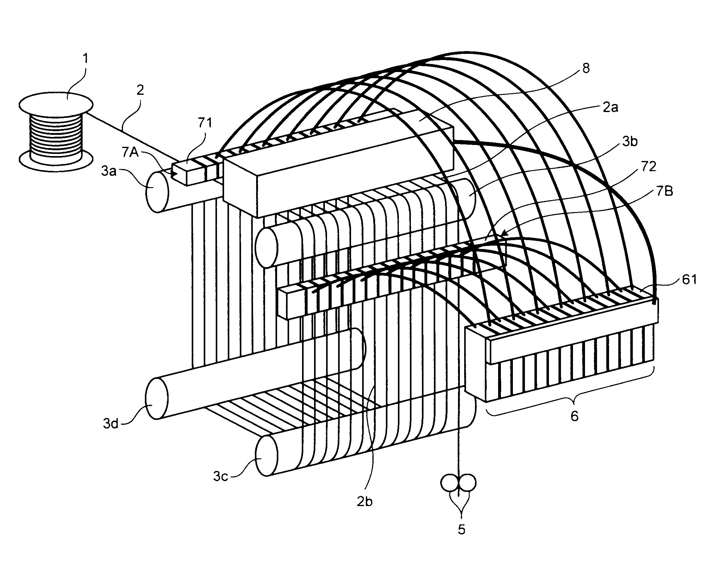
[0024]Configurations and operations according to embodiments of the present invention are explained below. FIG. 1 is a perspective view of a wire discharge-machining apparatus according to a first embodiment of the present invention. In the wire discharge-machining apparatus according to the first embodiment, a wire electrode 2 reeled out from a wire bobbin 1 is sequentially wound between plural guide rollers 3a to 3d at plural times with a small distance between wounded parts of the wire electrode 2, thereby forming plural cutting wires. A distance between cutting wires formed by winding the wire electrode 2 becomes a machining width (a wafer thickness) of a workpiece 8. That is, the workpiece 8 is cut in an electrically discharged manner by each cutting wire by cutting feeding the workpiece 8 to each cutting wire while supplying a voltage between each cutting wire and the workpiece 8 in a state that the workpiece 8 is set opposite to each cutting wire with a predetermined distance...
second embodiment
[0032]In the first embodiment described above, a system of preventing warping of the cutting wires 2a due to an electromagnetic force is explained. According to this system, one wire electrode 2 is wound between the plural guide rollers 3a to 3d to form the plural cutting wires 2a. The machining power source 6 and the feeders 7A and 7B are provided to individually feed power to each cutting wire 2a and to set directions of currents flowing to the cutting wires 2a mutually opposite between adjacent cutting wires 2a. That is, the system according to the first embodiment supplies power to the parallel cutting wires 2a such that flow directions of currents become mutually opposite between adjacent cutting wires 2a, thereby offsetting magnetic fields generated by the cutting wires 2a. This system can prevent warping of the cutting wires 2a due to an electromagnetic force, and can improve machining shape precision. In a second embodiment, a modification of the first embodiment to suppress...
third embodiment
[0038]In the first embodiment described above, a system of preventing warping of the cutting wires 2a due to an electromagnetic force is explained. According to this system, one wire electrode 2 is wound between the plural guide rollers 3a to 3d to form the plural cutting wires 2a. The machining power source 6 and the feeders 7A and 7B are provided to individually feed power to each cutting wire 2a and to set directions of currents flowing to the cutting wires 2a mutually opposite between adjacent cutting wires 2a. That is, the system according to the first embodiment supplies power to the parallel cutting wires 2a such that flow directions of currents become mutually opposite between adjacent cutting wires 2a, thereby offsetting magnetic fields generated by the cutting wires 2a. This system can prevent warping of the cutting wires 2a due to an electromagnetic force, and can improve machining shape precision.
[0039]In the second embodiment, in the power feeding system to the parallel...
PUM
| Property | Measurement | Unit |
|---|---|---|
| length | aaaaa | aaaaa |
| diameter | aaaaa | aaaaa |
| diameter | aaaaa | aaaaa |
Abstract
Description
Claims
Application Information
 - R&D
- Intellectual Property
- Life Sciences
- Materials
- Tech Scout
- Unparalleled Data Quality
- Higher Quality Content
- 60% Fewer Hallucinations
Browse by: Latest US Patents, China's latest patents, Technical Efficacy Thesaurus, Application Domain, Technology Topic, Popular Technical Reports.
© 2025 PatSnap. All rights reserved.Legal|Privacy policy|Modern Slavery Act Transparency Statement|Sitemap|About US| Contact US: help@patsnap.com


