
Hollow-fiber membrane module for moisture exchange

a technology of hollow fiber membrane and moisture exchange, which is applied in the direction of membranes, tobacco, electrochemical generators, etc., can solve the problems of excessive humidification of the electrochemical device, low humidification efficiency, and inability to densely fill the hollow fiber membrane in the humidifier, so as to reduce the flow of off-gas. the effect of the lowering of the hollow fiber membran

Active Publication Date: 2015-06-02
HONDA MOTOR CO LTD
View PDF30 Cites 1 Cited by
  • Summary
  • Abstract
  • Description
  • Claims
  • Application Information

AI Technical Summary

Benefits of technology

The solution enhances the humidifying efficiency by maintaining a stable membrane structure, ensuring uniform gas flow and increased contact area for moisture migration, thereby improving the overall performance of the fuel cell system.

Problems solved by technology

Therefore, when the fuel gas is humidified, the fuel electrode is excessively humidified, whereby a phenomenon called “flooding” occurs and prevents contact of the fuel with the fuel electrode.
Therefore, the contact area is small, whereby the moisture migration does not overtake the continuous supply of the oxidant gas, and humidifying efficiency is low.
Therefore, the hollow-fiber membranes must be filled in the humidifier by providing distances therebetween, and the hollow-fiber membranes cannot be densely filled in the humidifier.
The off-gas flows through the large spaces as bypasses and thereby does not uniformly flow within the humidifier, which decreases the humidifying efficiency.
However, it is difficult to prevent the imbalance of the hollow-fiber membranes within the area divided by the partition plate.
Moreover, since the partition plate cannot be formed into a completely closed structure in order to allow gas to flow, the imbalance of the hollow-fiber membranes at the open portion of the partition plate cannot be prevented.

Method used


Image

  • Hollow-fiber membrane module for moisture exchange
  • Hollow-fiber membrane module for moisture exchange
  • Hollow-fiber membrane module for moisture exchange

Examples


first embodiment

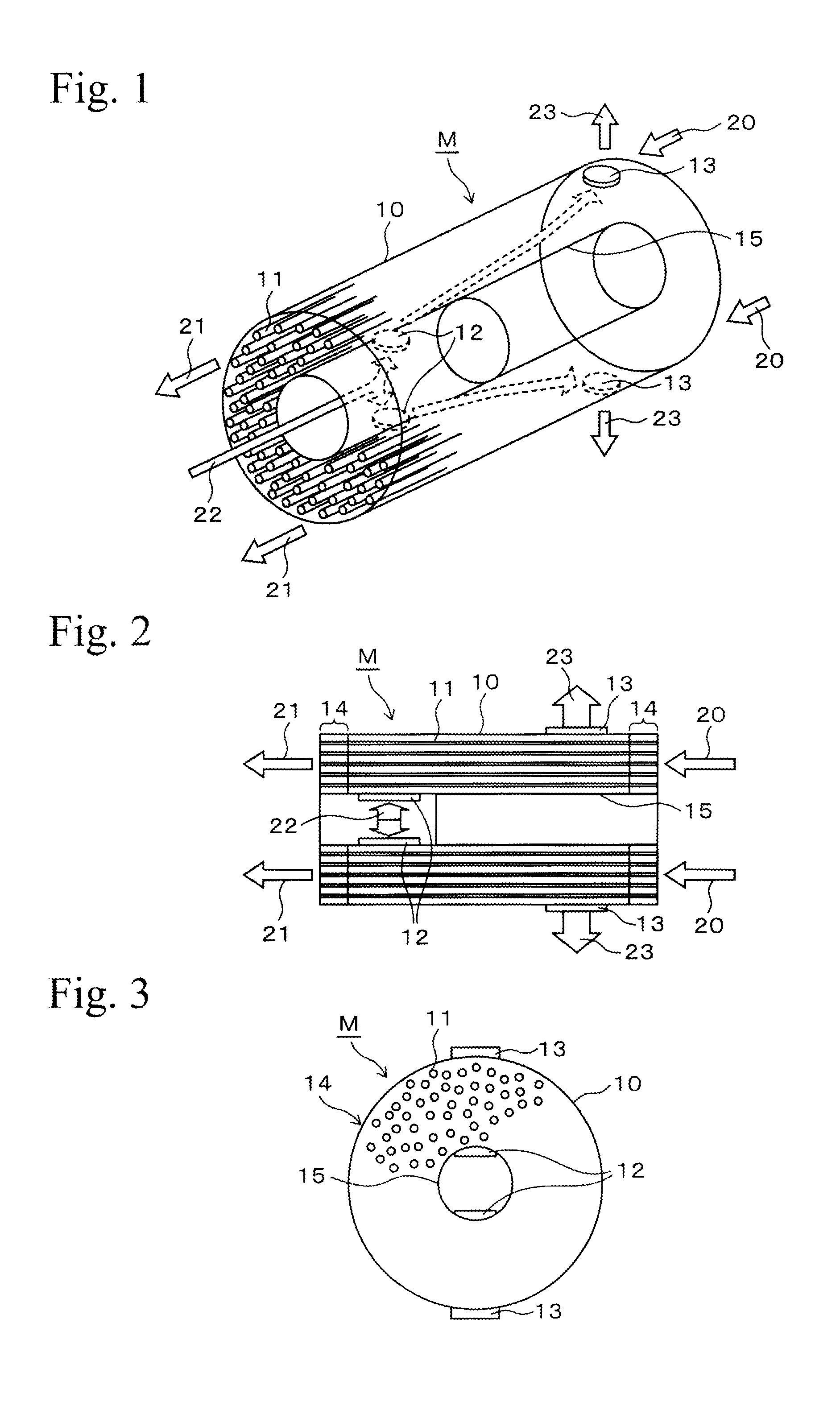
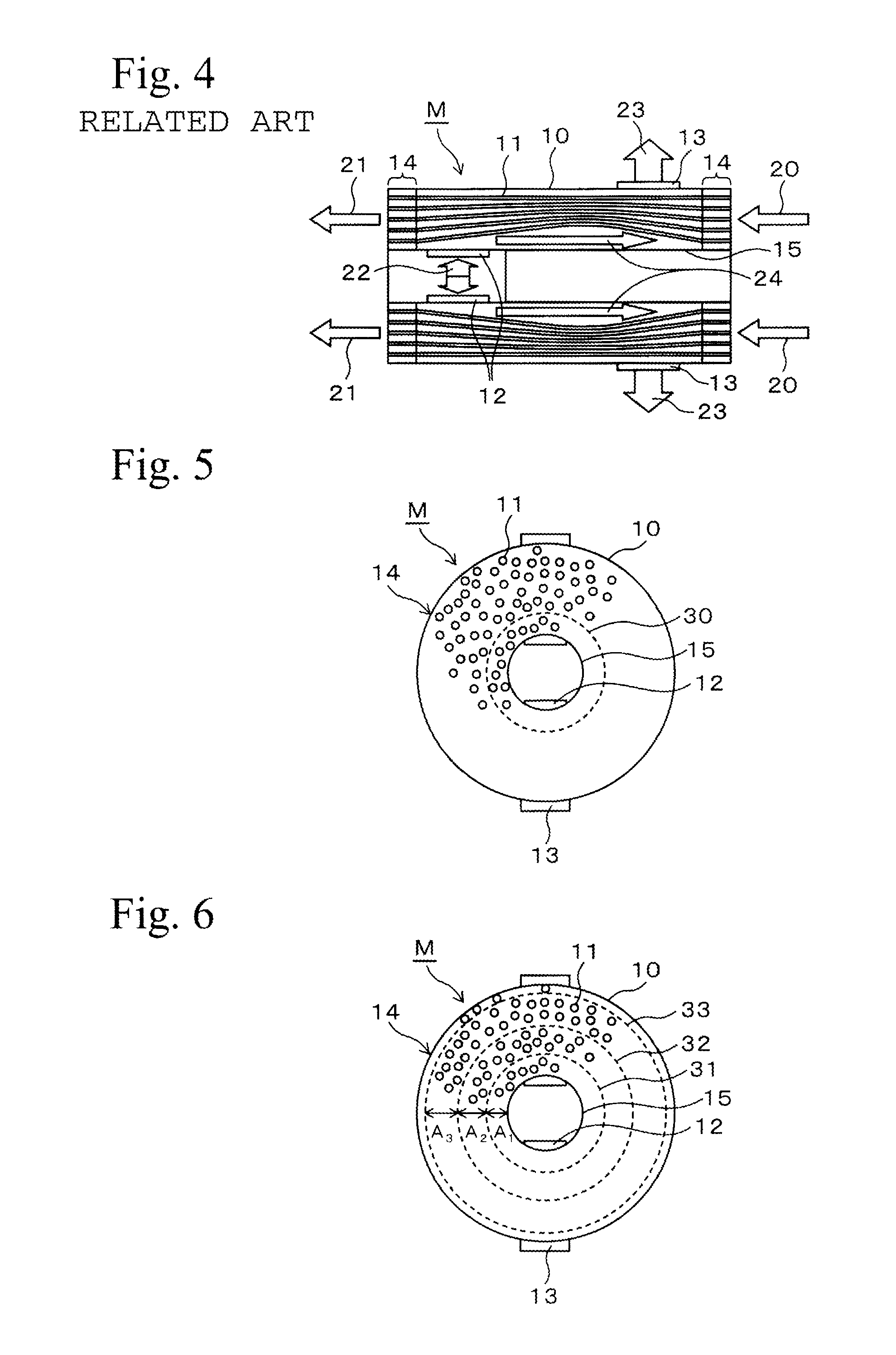
[0033]FIG. 5 shows an embodiment of a hollow-fiber membrane module for moisture exchange of the present invention, by which the above conventional problems can be solved. The hollow-fiber membrane module shown in FIG. 5 has the same components as those in FIGS. 1 to 3, except for a tubular porous member 30. Therefore, descriptions for the same components are omitted, and specific structure and effects in the First Embodiment will be described.

[0034]As shown in FIG. 5, the tubular porous member 30 is provided coaxially with the outer case 10 and the inner case 15 in the filling space, and it is inserted between the plural hollow-fiber membranes 11. The tubular porous member 30 has an opening ratio so as to let sufficient amount of the off-gas pass therethrough. The tubular porous member 30 has stiffness sufficient not to be deformed when it is subjected to the pressure of the off-gas, and it is made of a material that has good corrosion resistance for long periods. The tubular porous...

second embodiment

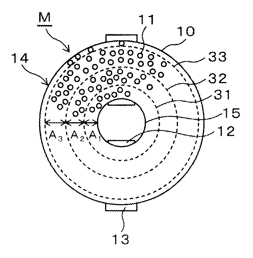
[0040]FIG. 6 shows another embodiment of a hollow-fiber membrane module for moisture exchange of the present invention, and FIG. 6 shows an example in which plural tubular porous members are provided. As shown in FIG. 6, in the filling space, a first tubular porous member 31, a second tubular porous member 32, and a third tubular porous member 33 are provided coaxially with the outer case 10 and the inner case 15. As in the case of the First Embodiment, the tubular porous members 31 to 33 are formed of a mesh made of metal with corrosion resistance or of plastic, and the tubular porous members 31 to 33 are fixed by burying both ends into the sealing portions 14.

[0041]In the embodiment, a distance between the inner case 15 and the first tubular porous member 31 is expressed as A1. In addition, a distance between the first tubular porous member 31 and the second tubular porous member 32 is expressed as A2, and a distance between the second tubular porous member 32 and the third tubula...


PUM

PropertyMeasurementUnit
diametersaaaaaaaaaa
exchange humidityaaaaaaaaaa
distancesaaaaaaaaaa

Abstract

A hollow-fiber membrane module for moisture exchange including a tubular outer case, a tubular inner case, plural hollow-fiber membranes, sealing portions, an inlet, an outlet, a first flow path, a second flow path, and a tubular porous member. The inner case is coaxially contained in the outer case so as to have a space therebetween. The hollow-fiber membranes are filled in the space and extend in the axial direction. The sealing portions are provided to both ends of the space so as to fix the plural hollow-fiber membranes and to seal the space. The first flow path extends from one end side of the hollow-fiber membranes to the other end side via insides of the hollow-fiber membranes. The second flow path extends from the inlet to the outlet via outsides of the hollow-fiber membranes in the space. The tubular porous member is inserted between the hollow-fiber membranes.

Description

TECHNICAL FIELD[0001]The present invention relates to a hollow-fiber membrane module for moisture exchange, which may be suitably used in a fuel cell system, for example. Specifically, the present invention relates to a technique for improving efficiency of humidifying a dry gas.BACKGROUND ART[0002]A fuel cell formed of a fuel cell stack is generally known. In the fuel cell stack, plural unit cells, for example, several hundred unit cells, are stacked. The unit cell has a laminated structure in which a separator is laminated on each side of a plate-shaped membrane electrode assembly (MEA). The MEA has a three-layer structure in which an electrolyte membrane, made of ion-exchange resin or the like, is held between a pair of electrodes. The pair of electrodes is made of a positive electrode (air electrode, cathode) and a negative electrode (fuel electrode, anode). In such a fuel cell, for example, a fuel gas is supplied to a gas flow path which faces a gas diffusion electrode at the s...

Claims


Application Information

Patent Timeline
Patent Type & Authority Patents(United States)
IPC IPC(8): B01F3/04B01D63/02H01M8/04
CPCH01M8/04171B01D63/02H01M8/04149B01D2313/10B01D2313/12Y02E60/50B01D63/033
Inventor KATAGIRI, TOSHIKATSUIKADA, HIROMOTOHIDAKA, YOHEI
Owner HONDA MOTOR CO LTD
Learn More