Oral cavity suction device

a suction device and oral cavity technology, applied in the direction of saliva removers, etc., can solve the problems of uncomfortable sensation for patients and useless ejectors, and achieve the effects of reducing discomfort for patients, gentle suction force, and reducing gag reflexes

Active Publication Date: 2015-06-02
REYES HARI MARK
View PDF4 Cites 4 Cited by
  • Summary
  • Abstract
  • Description
  • Claims
  • Application Information

AI Technical Summary

Benefits of technology

[0002]The saliva ejector of the present invention solves the aforementioned problems. Employing a tapered, ovate shape. The saliva ejector of the present invention resides along the left or right-side buccal mucosa allowing for full view of the oral cavity. Placement along the buccal mucosa also alleviates the patient's natural gag reflex, and having different sized suction orifices on two opposing faces ensures a strong suction field while providing a gentle suction force on the patient's buccal mucosa and inner cheek helping to secure the position of the saliva ejector within the patient's mouth, resulting in a more effective, yet gentler saliva ejector. The patient can easily adjust his bite without the removal of the ejector, as well as relieve the water / saliva from his mouth by simply closing his mouth, thereby allowing the dentist or hygienist to work without an assistant constantly providing suction. The saliva ejector of the present invention also maximizes the patient's comfort if he has lingual gum sensitivity, temporomandibular joint (TMJ) issues, or mandibular or maxillary tori; these regions are simply not contacted due to the ejector's unique geometry, and its placement within the mouth.

Problems solved by technology

If the tip of the suction tube contacts the patient's mouth tissue, it can suck the tissue into contact with the tip of the ejector, thereby rendering the ejector useless, since it is no longer removing excess saliva, water, and debris, not to mention causing a very uncomfortable sensation for the patient.

Method used


Image

  • Oral cavity suction device
  • Oral cavity suction device
  • Oral cavity suction device

Examples


Embodiment Construction

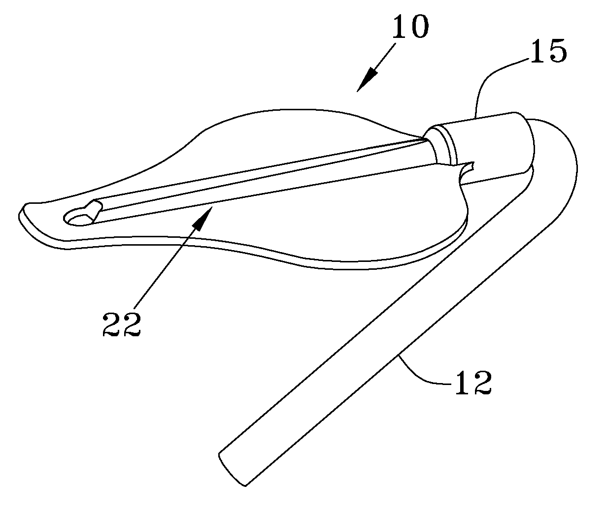
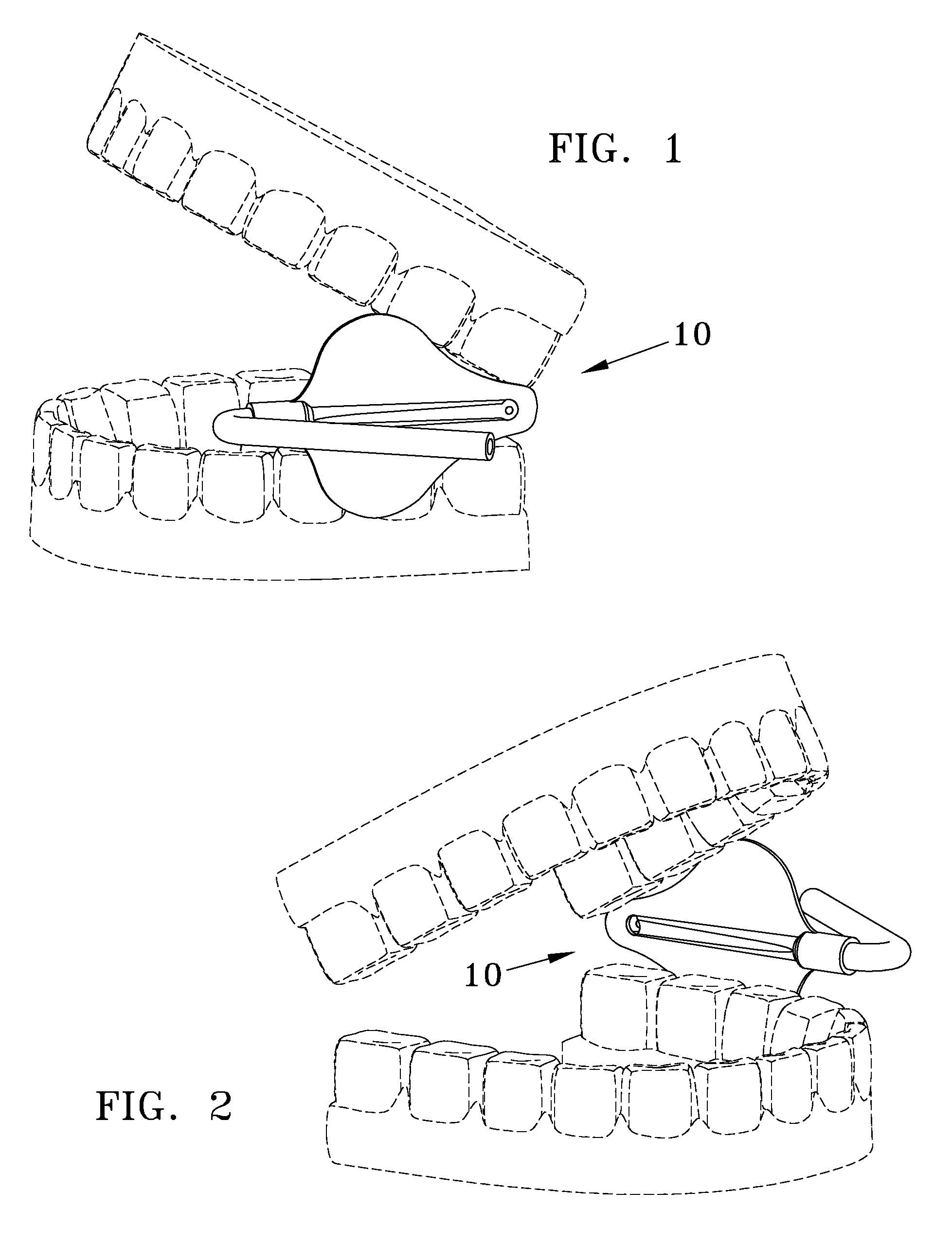
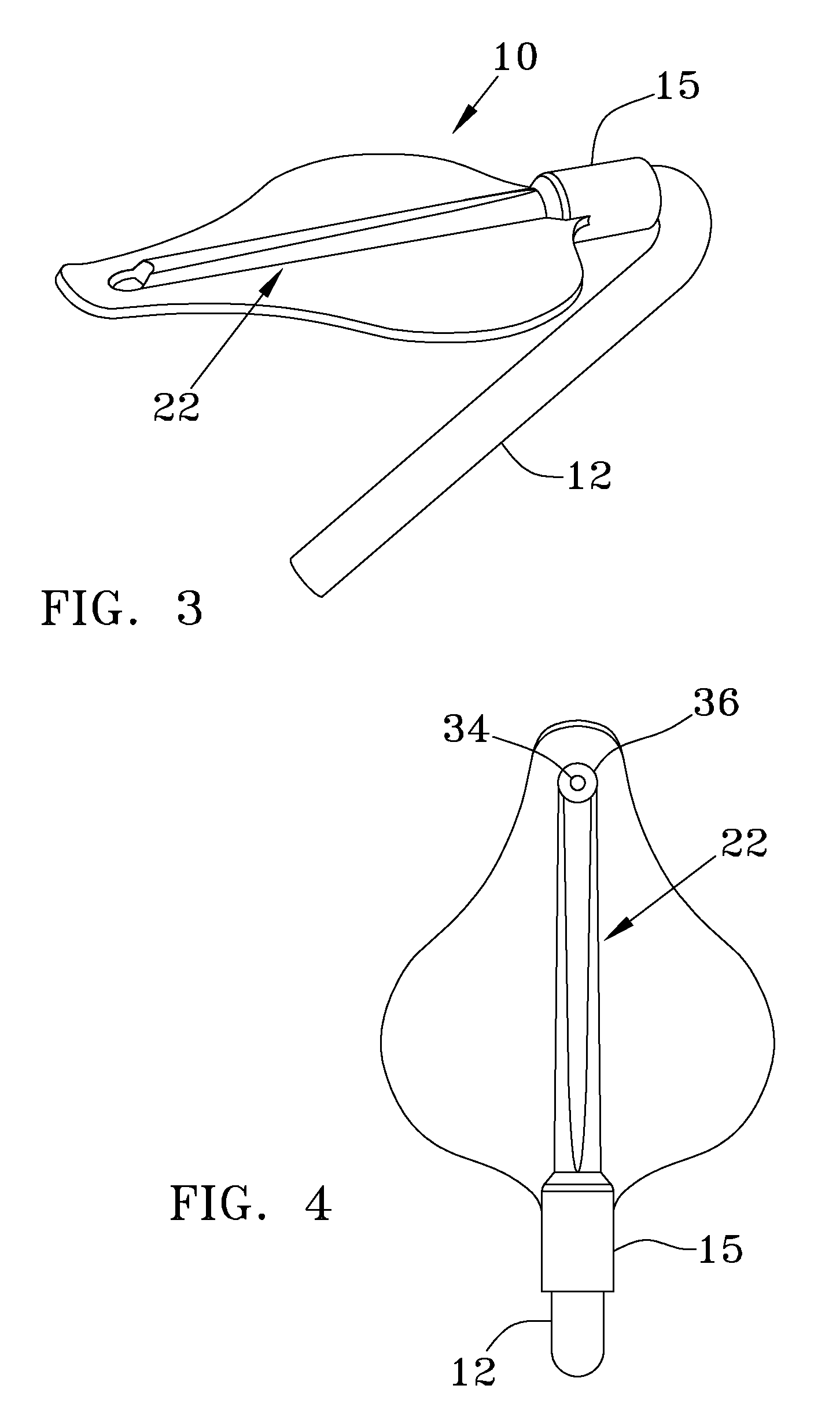
[0016]Referring to FIG. 1-7, saliva ejector 10 of the present invention is shown. Discharge tube 12 is made of any suitable food grade or medical polymer for medical devices or stainless steel. Tube 12 is hollow, has a proximate end 14, a distal end 16, and is generally cane-shaped, in that the included angle at proximate end 14 is acute, forming an approximate 32° angle (see FIGS. 12-13). Discharge tube 12 can be reusable or disposable. It is through discharge tube 12 that saliva ejector 10 is connected to a slow-speed suction device (well known in the art and not shown), and through which saliva, water, and other debris are removed from the mouth of a patient.

[0017]Discharge tube 12 is removeably engaged via friction fit connection sleeve 15 located at the high-end 18 of saliva ejector 10. Turning to FIG. 7 it can be seen that there is a gradual uniform taper along saliva ejection tube 22 between high-end / back end 18 and a low-end / front end 20. Saliva ejection tube 22 extends alon...


PUM


Abstract

A disposable saliva ejector for connection with a slow-speed suction device has a suction end and a discharge end. The tapered ejector has an ovate shape. A retention orifice helps secure the ejector within the patient's mount, while a larger extraction orifice removes fluid and debris. Placement of the saliva ejector within the mouth lies along the interior of the patient's cheek, keeping the oral cavity clear of viewing obstructions. The discharge end connects to a discharge tube, wrapping around the oral commissure then hooking onto the patient's outer cheek. Once properly placed within the patient's mouth the dental assistant is relieved from providing suction during various procedures.

Description

BACKGROUND OF THE INVENTION[0001]Saliva ejectors are narrow tubes that dental health professionals employ for removing saliva, water, and debris during a dental procedure. Often saliva ejectors will “sit” in a patient's mouth during a dental procedure in order to continuously rid the mouth of excess saliva, water, and debris to facilitate uninterrupted work by the dental health professional. The ejector tubes are typically made of a pliable plastic with a metal wire embedded within its wall to allow the tube to be bent to a desired angle and maintain that angle. If the tip of the suction tube contacts the patient's mouth tissue, it can suck the tissue into contact with the tip of the ejector, thereby rendering the ejector useless, since it is no longer removing excess saliva, water, and debris, not to mention causing a very uncomfortable sensation for the patient. Due to this fact the dentist preforming the work on the patient must be assisted at all times.SUMMARY OF THE INVENTION[0...

Claims


Application Information

Patent Timeline
Patent Type & Authority Patents(United States)
IPC IPC(8): A61C17/06
CPCA61C17/043A61C17/08
Inventor REYES, HARI MARK
Owner REYES HARI MARK
Why Eureka
Try Eureka