Oral Cavity Suction Device

a suction device and oral cavity technology, applied in the field of oral cavity suction devices, can solve the problems of reducing the patient's comfort and discomfort, and useless ejectors, and achieve the effects of less if any attention, effective, gentler and comfortable saliva ejectors, and reducing patient's natural gag reflex

Active Publication Date: 2017-06-08
REYES HARI MARK
View PDF3 Cites 11 Cited by
  • Summary
  • Abstract
  • Description
  • Claims
  • Application Information

AI Technical Summary

Benefits of technology

[0006]The saliva ejector of the present invention solves the aforementioned problems by employing a tapered, ovate shape. The saliva ejector of the present invention resides along the left or right-side buccal mucosa allowing for full view of the oral cavity. When the device is positioned along the buccal mucosa, it alleviates the patient's natural gag reflex, and is out of the way of most dental procedures. Since it has a plethora of arced passaged formed about the perimeter of the device when assembled, and is non collapsible, it provides a continual strong suction field where it is needed, yet does not tug on the patient's buccal mucosa and inner cheek. The ejector's slender profile aids in positioning the saliva ejector within the patient's mouth, resulting in a more effective, gentler and comfortable saliva ejector. When coupled to a suction tube with a “U” bend, the combination may be placed adjacent the outside of the patient's cheek with the remaining tubing running back below the patient's ear such that the entire oral cavity suction system (the saliva ejector, the vacuum and the suction tube) is out of the dentist's way and requires little if any attention.
[0007]The patient can easily adjust his bite without the removal of the suction system, as well as relieve the water / saliva from his mouth by simply closing his mouth, thereby allowing the dentist or hygienist to work without an assistant constantly providing suction.
[0008]The saliva ejector of the present invention also maximizes the patient's comfort if he has lingual gum sensitivity, temporomandibular joint (TMJ) issues, or mandibular or maxillary tori; these regions are simply not contacted due to the devices's unique geometry, and its placement within the mouth.
[0009]The saliva ejector of the present invention allows simplified fabrication and assembly of the device. It allows a planar fabrication and assembly about the axial centerline of the device. The processes utilized in fabrication are simplified and the number of fabrication steps are reduced.

Problems solved by technology

If the tip of the suction tube contacts the patient's mouth tissue, it can suck the tissue into contact with the tip of the ejector, thereby rendering the ejector useless, since it is no longer removing excess saliva, water, and debris, not to mention causing a very uncomfortable sensation for the patient.

Method used


Image

  • Oral Cavity Suction Device
  • Oral Cavity Suction Device
  • Oral Cavity Suction Device

Examples


Embodiment Construction

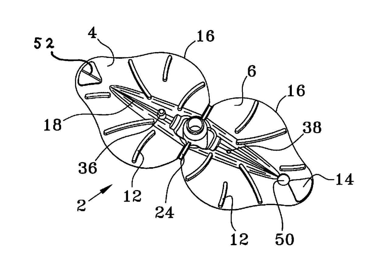
[0021]Looking at FIG. 1 it can be seen that the saliva ejector 2 is a pair of substantially similar leaf shaped (ovate) plates with their proximal ends hingedly connected together into a mirror image configuration with a short tube extending normally above and below the plates from a cutout region at the center of the ejector's axial centerline, where the two plates are conjoined. However, upon closer examination it can be seen that this device is much more structurally complex as will be discussed herein.

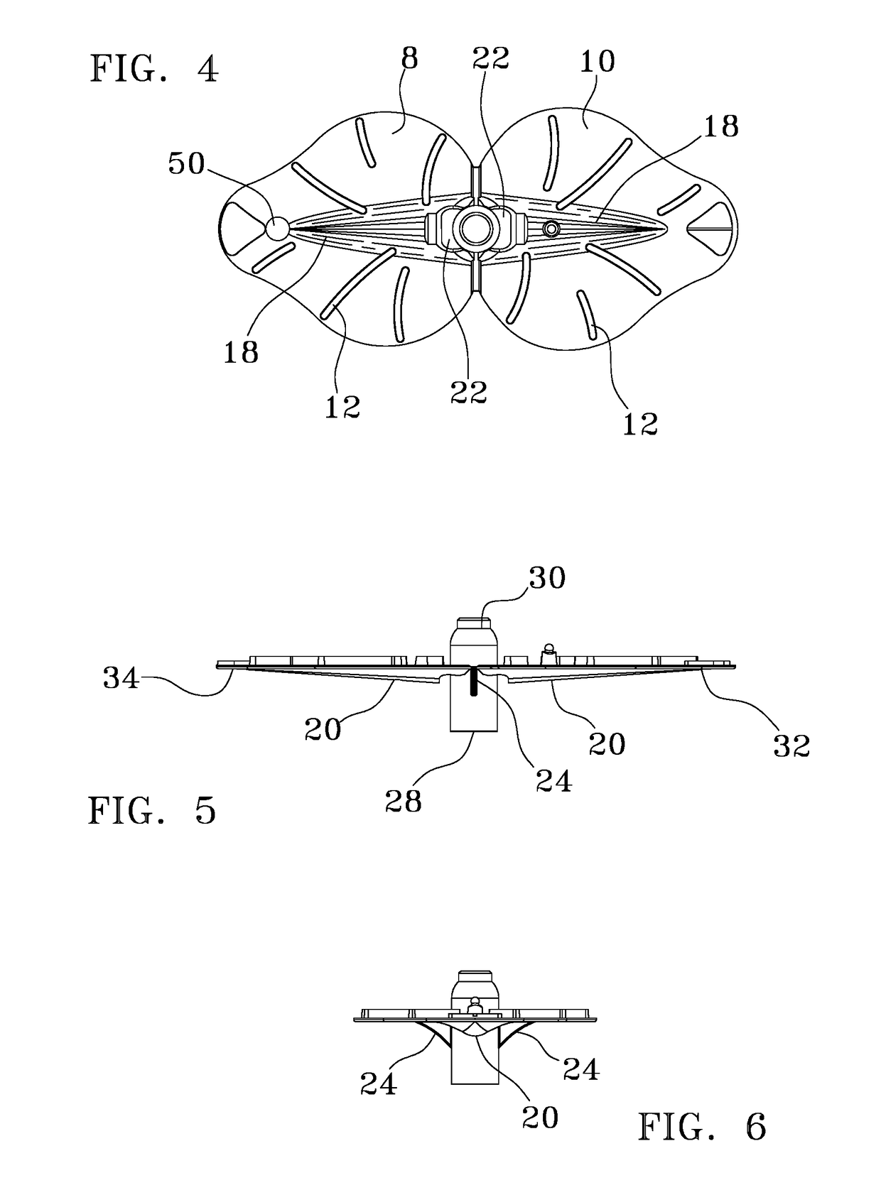
[0022]There is a unique geometry to the saliva ejector 2, which can generally be described as ovate (i.e., having a wider base than apex and referred to herein also as a leaf shape), such that each plate has two distinct regions, its body 1, and its front lobe 3 (FIG. 8). Combined, these regions are referred to as leaf shaped plates. Each plate is a flexible, generally planar member that is constructed from a medical grade polymer of uniform thickness.

[0023]The saliva ejector 2 is ...


PUM


Abstract

A disposable saliva ejector made by a simplified manufacturing design that utilizes a single planar, double leaf shaped plate design that is embossed on the inner faces of the leaf plates with a series of arced ribs and then folded about its midpoint. A tab and slot arrangement joins the two plates such that the distal and proximal tips meet and can be held in operational contact by the suction forces passed through the device and via a tab and slot arrangement. The arced ribs then form a series of channels that are equally spaced about perimeter of the device. A trough runs along the linear axis of both of the plates to direct any fluid and debris that is sucked into the channels into a connected suction tube. Placement of the saliva ejector within the mouth lies along the interior of the patient's cheek, keeping the oral cavity clear of viewing obstructions. The discharge end connects to a discharge tube, wrapping around the oral commissure then hooking onto the patient's outer cheek. Once properly placed within the patient's mouth the dental assistant is relieved from providing suction during various procedures.

Description

COPYRIGHT STATEMENT[0001]A portion of the disclosure of this patent document contains material that is subject to copyright protection. The copyright owner has no objection to the facsimile reproduction by anyone of the patent document or the patent disclosure as it appears in the Patent and Trademark Office patent file or records, but otherwise reserves all copyright rights whatsoever.FIELD[0002]The present disclosure relates, in general, to an oral cavity suction device, and more particularly to a dental saliva ejection device.BACKGROUND[0003]Oral cavity suction devices, also known as saliva ejectors are narrow vacuum tubes that dental health professionals employ for removing saliva, water, and debris during a dental procedure. Often saliva ejectors will “sit” in a patient's mouth during a dental procedure in order to continuously rid the mouth of excess saliva, water, and debris to facilitate uninterrupted work by the dental health professional. The ejector tubes are typically ma...

Claims


Application Information

Patent Timeline
Patent Type & Authority Applications(United States)
IPC IPC(8): A61C17/06A61C5/14
CPCA61C5/14A61C17/043A61C17/08A61C5/90
Inventor REYES, HARI MARK
Owner REYES HARI MARK
Why Eureka
Try Eureka