Relief valve device
a valve device and valve body technology, applied in the direction of valve operating means/releasing devices, mechanical equipment, transportation and packaging, etc., can solve the problems of complex structure and mechanism, difficult to guarantee operation, and need for high-precision machining and assembly, so as to reduce the number of components, simple structure, and simple mechanism
- Summary
- Abstract
- Description
- Claims
- Application Information
AI Technical Summary
Benefits of technology
Problems solved by technology
Method used
Image
Examples
first embodiment
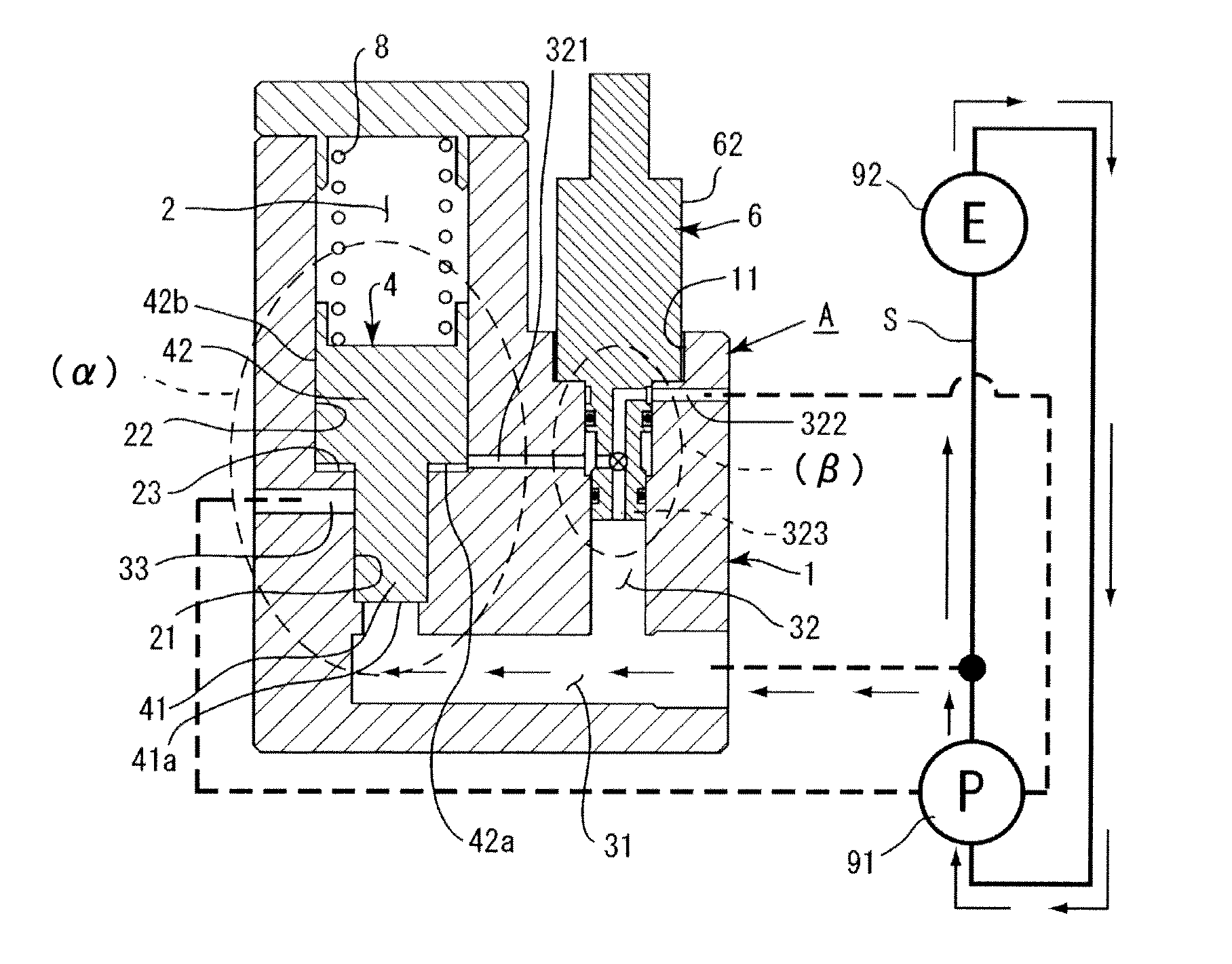
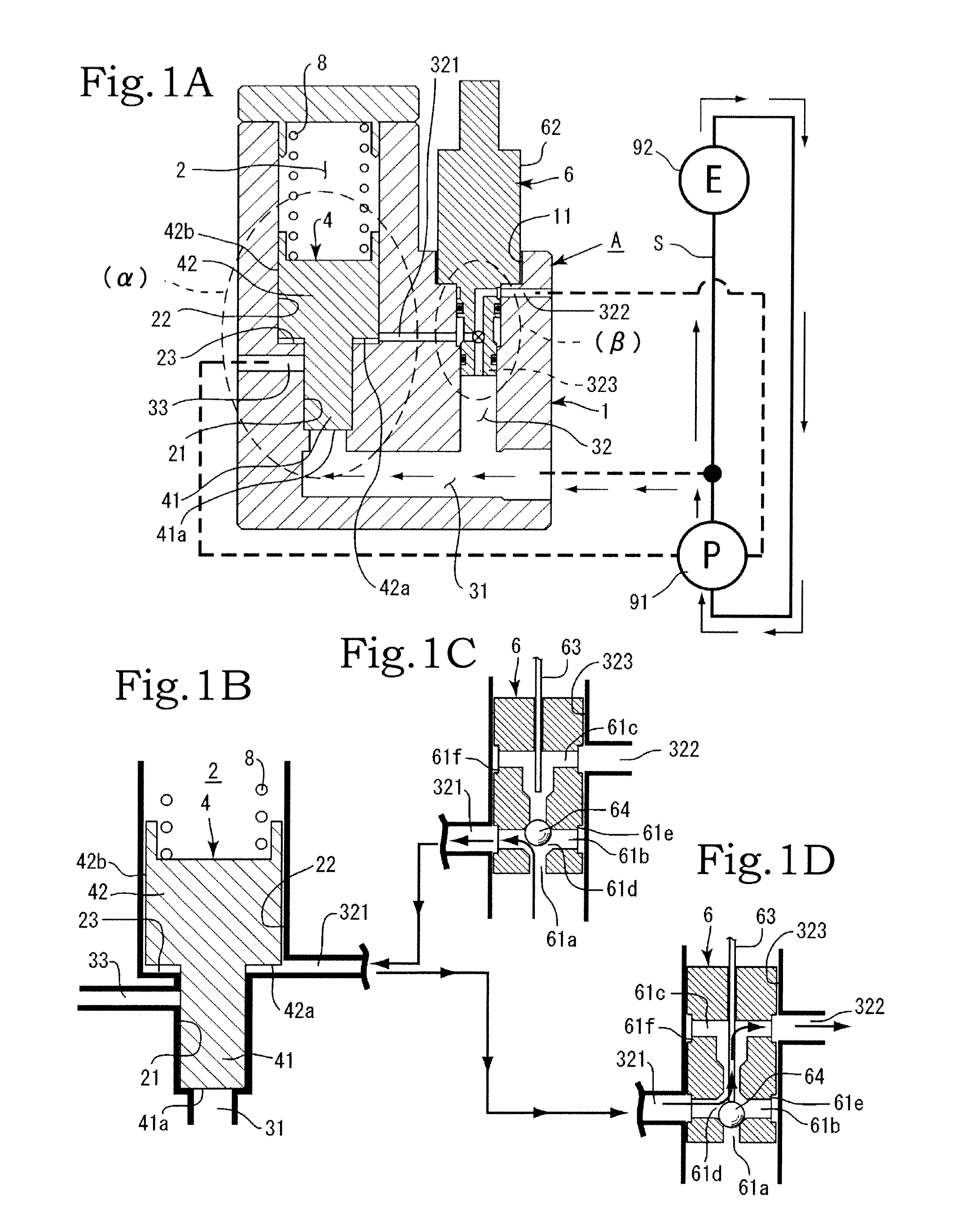
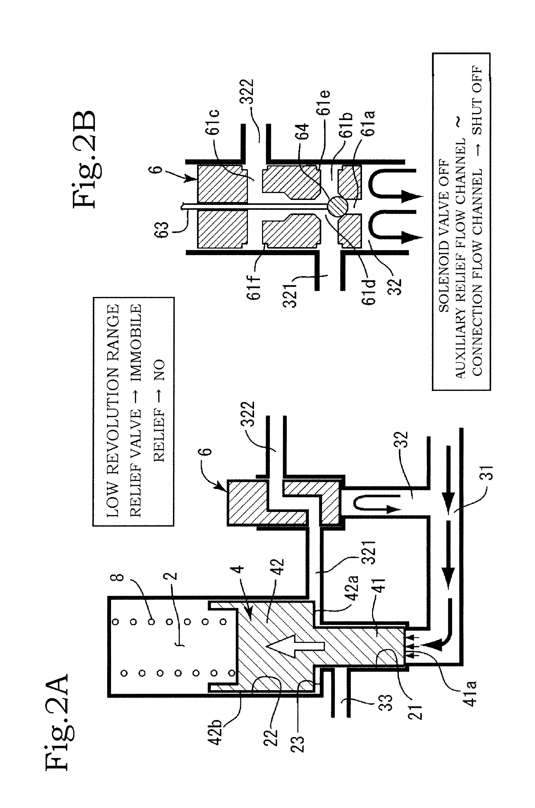
[0026]Embodiments of the present invention are described below with reference to accompanying drawings. The present invention has a plurality of embodiments. A first embodiment will be explained first. The configuration of the present invention comprises mainly a housing A, a solenoid valve 6, a relief valve 4 and a spring 8. The solenoid valve 6 is mounted on a chassis 1 of the housing A. The relief valve 4 is accommodated in the chassis 1 (FIG. 1A).
[0027]In the chassis 1 there are formed, for instance, a valve passage 2, a main relief flow channel 31, an auxiliary relief flow channel 32 and the like. The valve passage 2 is a site at which the relief valve 4 is accommodated. The valve passage 2 comprises a small-diameter passage section 21 and a large-diameter passage section 22 that are formed as coaxial cylindrical shapes having dissimilar inner diameters. Specifically, the large-diameter passage section 22 having a large diameter dimension is formed on the opening side, and the ...
second embodiment
[0063]the present invention is explained next with reference to FIG. 8. An in-valve flow channel 43 is formed inside the relief valve 4. The in-valve flow channel 43, specifically, is a flow channel that is formed extending from the main pressure-receiving surface 41a of the small-diameter section 41 over the outer peripheral side face 42b of the large-diameter section 42 (for instance, FIGS. 8A, 8C).
[0064]The in-valve flow channel 43 is made up of an axial direction flow channel 43a and a diameter-direction flow channel 43b, such that the axial direction flow channel 43a and the diameter-directs channel 43b communicate with each other. A flow channel opening of the axial direction flow channel 43a is positioned at the main pressure-receiving surface 41a of the small-diameter section 41, and flow channel openings of the diameter-direction flow channel 43b are positioned at the outer peripheral side face 42b of the large-diameter section 42.
[0065]The function (effect) of the in-valve...
PUM
 Abstract
Description
Claims
Application Information
 - R&D
- Intellectual Property
- Life Sciences
- Materials
- Tech Scout
- Unparalleled Data Quality
- Higher Quality Content
- 60% Fewer Hallucinations
Browse by: Latest US Patents, China's latest patents, Technical Efficacy Thesaurus, Application Domain, Technology Topic, Popular Technical Reports.
© 2025 PatSnap. All rights reserved.Legal|Privacy policy|Modern Slavery Act Transparency Statement|Sitemap|About US| Contact US: help@patsnap.com


