
Hair clipper with a rotary motor vibration and noise damper

a rotary motor and hair clipper technology, applied in the direction of metal working apparatuses, etc., can solve the problems of resonating inside the housing, amplifying noise, and undesirable both vibration and nois

Active Publication Date: 2015-05-26
WAHL CLIPPER
View PDF30 Cites 37 Cited by
  • Summary
  • Abstract
  • Description
  • Claims
  • Application Information

AI Technical Summary

Benefits of technology

[0034]The advantages of this invention are now apparent. Both vibration and noise are reduced as compared with the vibration and noise generated by conventional hair clippers.

Problems solved by technology

However, if the housing is significantly larger than the motor (creating a large dead air space) or the motor has significant clearance between the shaft and bearing, the motor vibration tends to resonate inside the housing causing amplified noise.
Both vibration and noise are undesirable.
Vibration and noise occur in rotary motor hair clippers, where an eccentric cam drives a blade along a linear reciprocating path.
The eccentricity of the cam causes resonant frequencies at the points of contact between the motor and the housing, and transfers energy into vibration and noise that the user feels while the hair clipper is in use.

Method used


Image

  • Hair clipper with a rotary motor vibration and noise damper
  • Hair clipper with a rotary motor vibration and noise damper
  • Hair clipper with a rotary motor vibration and noise damper

Examples


Embodiment Construction

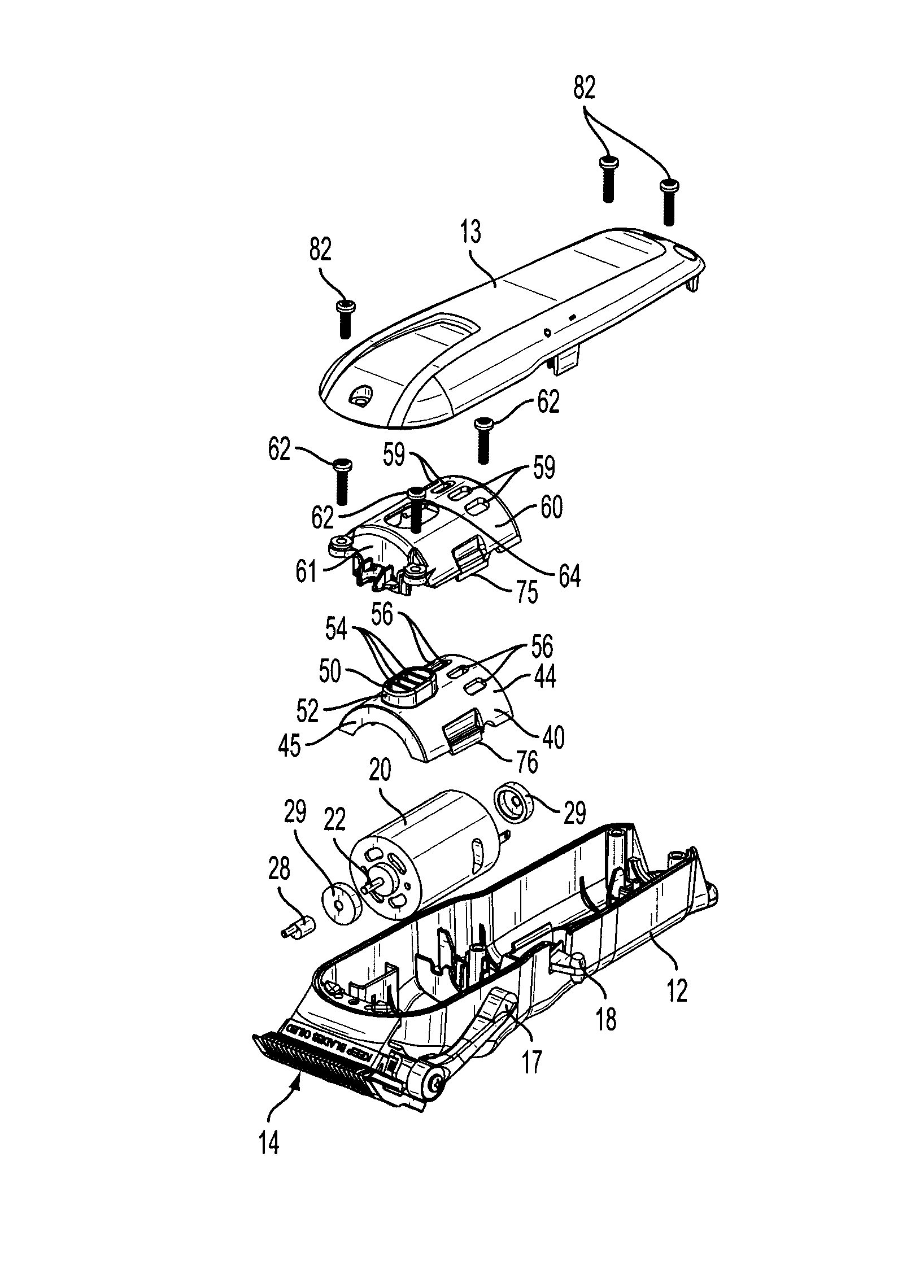
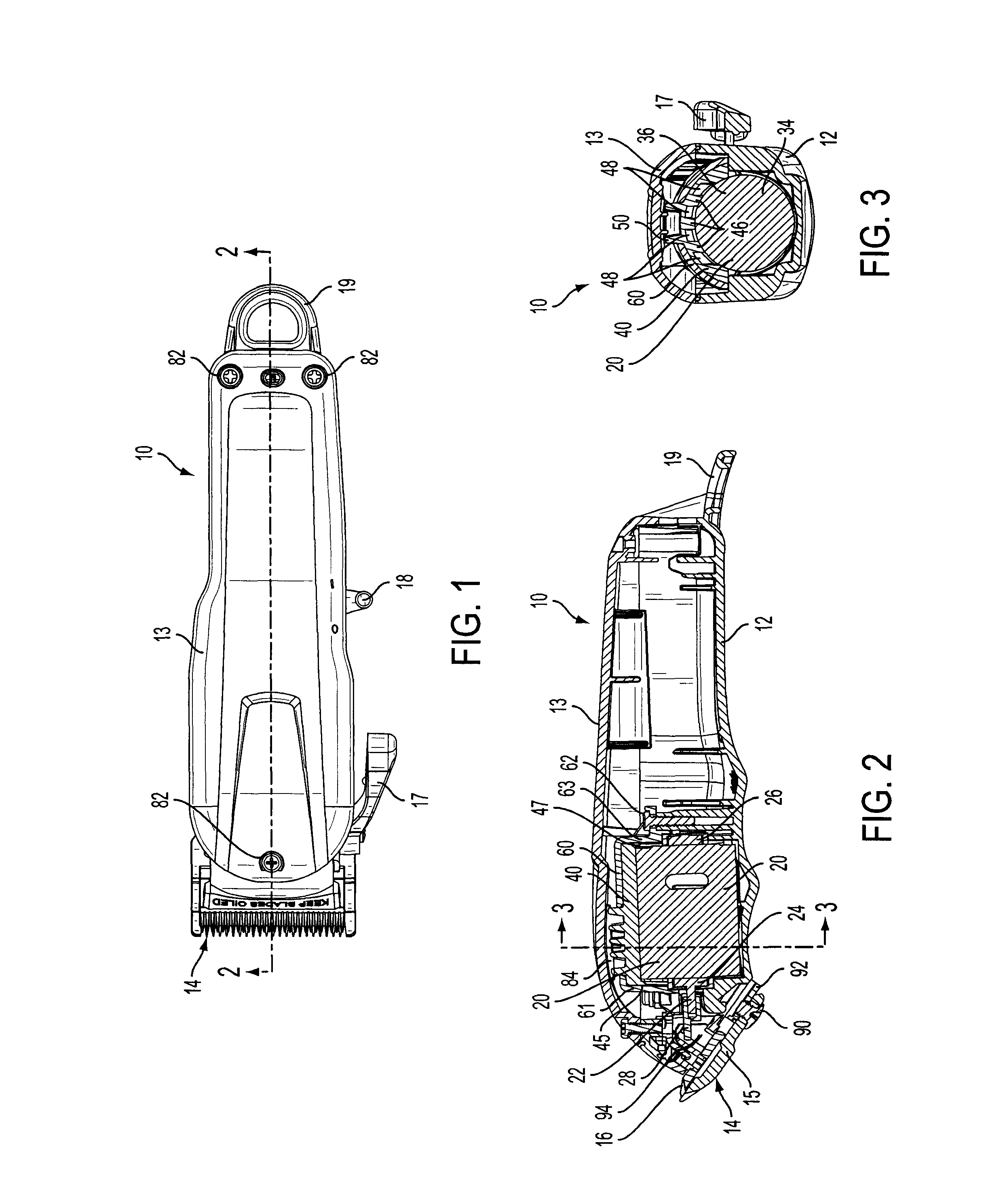
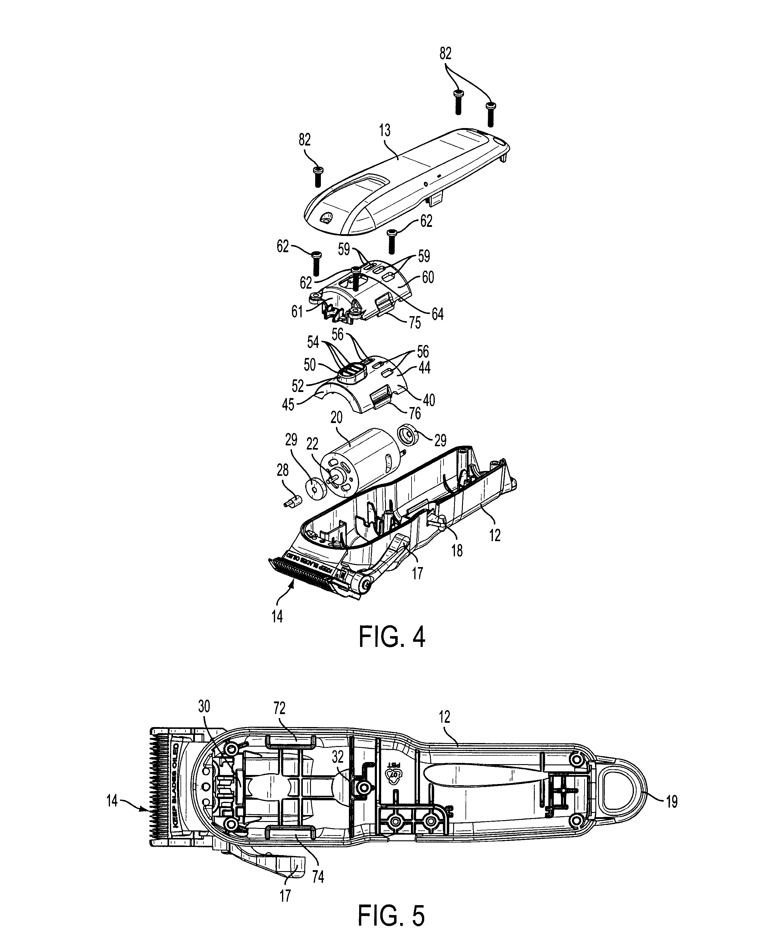
[0018]As seen in FIGS. 1, 2 and 3, a hair clipper 10 has a base structural housing 12 and a secondary housing cover 13. The base structural housing 12 and the secondary housing cover 13 can be relatively simple in construction, but preferably are not prone to excessively vibrate, resonate or amplify noise.

[0019]A blade set 14 includes a stationary blade 15 and a reciprocating blade 16. A blade depth adjuster 17, a motor switch 18 and a clipper hanger hook 19 are provided. A power source such as a battery or line cord and appropriate wiring (not shown) are also provided.

[0020]A rotary motor 20 has a shaft 22 (FIG. 4) extending through the motor 20 between a front bearing 24 (FIG. 2) and a rear bearing 26. A rubber collar 29 can be provided over each of the bearings to absorb vibration and reduce noise. The shaft 22 has a cam 28 near the front bearing 24 for driving the reciprocating blade 16.

[0021]Turning briefly to FIG. 5, the base structural housing 12 has at least one support for ...


PUM


Abstract

A hair clipper has a base structural housing with a blade set operably secured thereto. The blade set has a stationary blade and a reciprocating blade. The base has at least one support for a rotary motor. A flexible motor vibration and noise damper fits over half of the motor, and a motor cover is secured to the base structural housing over the vibration damper. A secondary housing cover is secured to the base structural housing over the motor cover.

Description

[0001]This invention relates to hair clippers, and more particularly to motor vibration and noise dampening for hair clippers driven by a rotary motor with an eccentric cam mechanism converting rotary motion into linear motion of a reciprocating blade.BACKGROUND OF THE INVENTION[0002]Many hand held tools are designed to hold or support a motor in a rigid housing around the motor's front and rear motor bearings. To suppress vibration transferring to the housings, a thin rubber collar is used around the circumference of the bearings. For additional vibration reduction, a piece of sponge rubber is often used between the motor and housing under light compression. However, if the housing is significantly larger than the motor (creating a large dead air space) or the motor has significant clearance between the shaft and bearing, the motor vibration tends to resonate inside the housing causing amplified noise. Both vibration and noise are undesirable.[0003]Vibration and noise occur in rota...

Claims


Application Information

Patent Timeline
Patent Type & Authority Patents(United States)
IPC IPC(8): B26B19/06B26B19/28B26B19/38
CPCB26B19/06B26B19/3866B26B19/28B26B19/3853
Inventor ARNDT, STEVENGESIAKOWSKI, JEFF
Owner WAHL CLIPPER
Learn More