
Audio signal correction and calibration for a room environment

a technology for audio signal correction and room environment, applied in the direction of frequency response correction, resonant transducer, prosthesis, etc., can solve the problems of not only frequency distortion but reverberation, room modifies the signal heard by the listener from what was originally, and reduces sound quality and intelligibility

Active Publication Date: 2015-05-19
HARMAN PROFESSIONAL INC
View PDF11 Cites 4 Cited by
  • Summary
  • Abstract
  • Description
  • Claims
  • Application Information

AI Technical Summary

Benefits of technology

This patent is about a method and apparatus for processing audio signals in a room to create a better listening experience. The method involves recording the audio signal and processing it to create a more accurate frequency response. This helps to adjust the audio signals to match the characteristics of the room, resulting in a more pleasant listening experience for the user. The technical effect of this patent is an improved quality of audio signals in a room setting, making it easier to produce and enjoy music or spoken words.

Problems solved by technology

However, when such high quality CDs or DVDs are played in a typical room, the room modifies the signal heard by the listener from what was originally intended.
However, at higher frequencies reflections from walls, ceilings and floors cause not only frequency distortion but reverberation and in extreme cases a discrete echo can be heard.
The low frequency room modes can also cause very slow decay of sound notes which masks sounds near its frequency, which reduces the sound quality and intelligibility.
However, this is not possible if the room has already been designed.
However, this can be very expensive to do or may not be viable when the room is a conference room or a room used for multiple purposes or living in general.
Also, the frequency overlapping nature of the 33-band graphic equalizer makes it difficult to dial-in a correction.
However, none of these early attempts have successfully optimized sound quality.
In-fact, such audio conventional correction efforts have even worsened the sound quality in certain circumstances.

Method used


Image

  • Audio signal correction and calibration for a room environment
  • Audio signal correction and calibration for a room environment
  • Audio signal correction and calibration for a room environment

Examples


Embodiment Construction

[0031]It will be readily understood that the components of the present application, as generally described and illustrated in the figures herein, may be arranged and designed in a wide variety of different configurations. Thus, the following detailed description of the embodiments of a method, apparatus, and system, as represented in the attached figures, is not intended to limit the scope of the invention as claimed, but is merely representative of selected embodiments of the invention.

[0032]The features, structures, or characteristics of the invention described throughout this specification may be combined in any suitable manner in one or more embodiments. For example, the usage of the phrases “example embodiments”, “some embodiments”, or other similar language, throughout this specification refers to the fact that a particular feature, structure, or characteristic described in connection with the embodiment may be included in at least one embodiment of the present invention. Thus...


PUM


Abstract

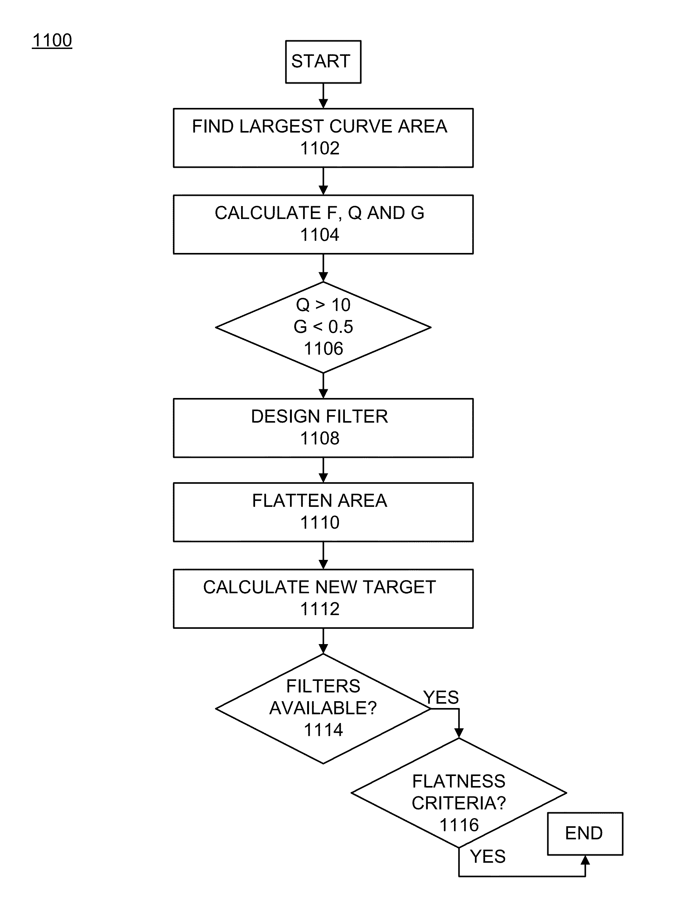
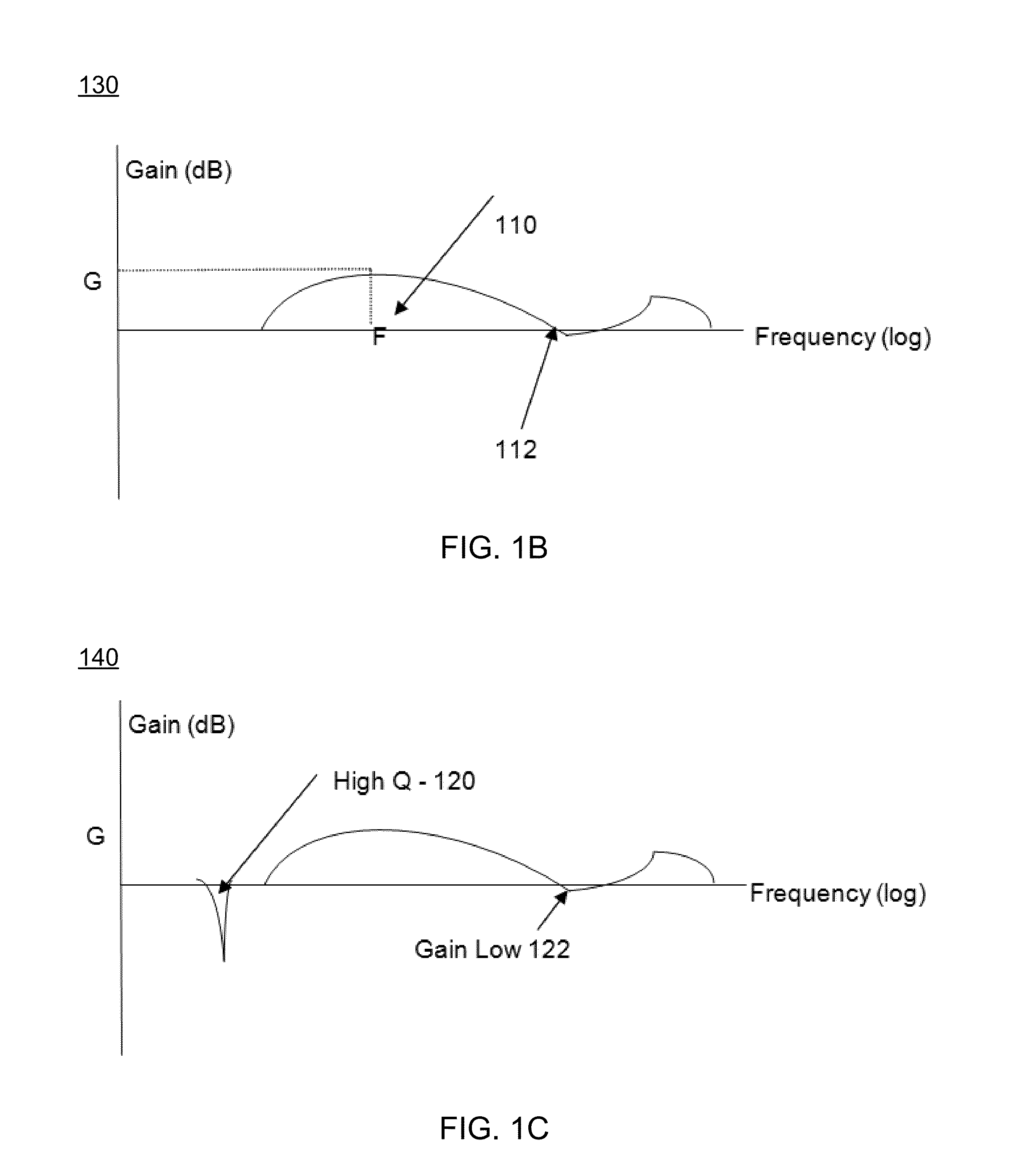
Disclosed are an apparatus and method of processing an audio signal to optimize audio for a room environment. One example method of operation may include recording the audio signal generated within a particular room environment and processing the audio signal to create an original frequency response based on the audio signal. The method may also include identifying a target sub-region of the frequency response which has a predetermined area percentage of a total area under a curve generated by the frequency response, determining whether the target sub-region is a narrow energy region, creating a filter to adjust the frequency response, and applying the filter to the audio signal.

Description

TECHNICAL FIELD OF THE INVENTION[0001]This invention relates to a method and apparatus of performing audio correction and calibration for a reverberant room environment to reduce feedback and optimize audio capabilities.BACKGROUND OF THE INVENTION[0002]All audio systems are affected by the environment or room in which they are installed. For example, digital audio sources, such as compact discs and other types of discs (e.g., CDs and DVDs) have a + / −0.001 dB flat frequency response from 20 Hz to 20 kHz. Such audio sources also have a high S / N ratio of >100 dB, and negligibly low distortion levels of THD 0.001% at full scale. In addition, the digital signals are free from transient distortion, reverberation as well as ‘wow’ or ‘flutter’. However, when such high quality CDs or DVDs are played in a typical room, the room modifies the signal heard by the listener from what was originally intended. The speaker is responsible for some frequency deviation from the flat response and incr...

Claims


Application Information

Patent Timeline
Patent Type & Authority Patents(United States)
IPC IPC(8): H04B3/20A61F2/76H03F1/06H03F3/181H03F3/189H03F3/66H03G5/16H04R1/20H04R1/22H04R1/24H04R1/26H04R3/04H04R9/18H04R11/14H04R15/02H04R17/10H04R25/00H04S7/00
CPCH03G5/165H03F1/06H03F3/181H03F3/189H03F3/66H04R1/20H04R1/22H04R1/227H04R1/24H04R1/26H04R3/04H04R9/18H04R11/14H04R15/02H04R17/10H04R25/353H04R25/48H04R25/558H04S7/307A61F2002/765H03F2200/333H03F2200/348H03F2200/429H03F2200/451H03F2203/45264H04R2201/028H04R2205/021H04R2205/026H04R2227/005H04S2400/07
Inventor NACKVI, FAWAD
Owner HARMAN PROFESSIONAL INC
Learn More