
System and method for detecting rock fall

a technology of rock fall and detection method, which is applied in the direction of setting time indication, electric unknown time interval measurement, amplifier modification to reduce noise influence, etc., can solve the problems of affecting the safety of passengers, and causing significant damage to the train

Active Publication Date: 2015-05-12
WEIR JONES ENG CONSULTANTS
View PDF19 Cites 15 Cited by
  • Summary
  • Abstract
  • Description
  • Claims
  • Application Information

AI Technical Summary

Benefits of technology

The invention is a system for detecting rock fall near a section of railway track. It consists of multiple ballast sensors placed along the track section, which are sensitive to sound waves and can detect any acoustic energy. These sensors are located in the ballast, which is near the track but separated from the rails and ties. The system also includes a signal processing unit that receives the ballast sensor signals. The method involves processing the signals to detect rock fall events in the vicinity of the track section based on the ballast sensor signals. The technical effect of this invention is the ability to detect and locate rock fall near a railway track, which can help prevent accidents and minimize damage to infrastructure.

Problems solved by technology

Rock fall events and other similar events (e.g. avalanches and washouts) which take place in a vicinity of railway tracks can damage the track, can damage passing trains and, in some cases, can derail passing trains which can in turn cause significant damage to the train and to people and / or property being transported by the train.
Damaged trains can cause corresponding damage to the environment.
Similar events which take place in a vicinity of other transport-ways (e.g. roadways, bridges, subway tracks and the like) can cause similar damage.
Falling rock may strike and break one or more of these wires, opening the corresponding circuits and preventing current flow therethrough.
Slide fences are unreliable, because falling rock may not strike or break a wire, but may still represent a danger to a passing train.
Slide fences also tend to generate false positive results, for example, when the wire are broken by animals or the like.
Additionally, if a slide fence triggers (i.e. a wire is broken), then the slide fence must be repaired (i.e. the broken wire must be replaced) and rail traffic may be delayed until the slide fence is repaired.

Method used


Image

  • System and method for detecting rock fall
  • System and method for detecting rock fall
  • System and method for detecting rock fall

Examples


Embodiment Construction

[0039]Throughout the following description, specific details are set forth in order to provide a more thorough understanding of the invention. However, the invention may be practiced without these particulars. In other instances, well known elements have not been shown or described in detail to avoid unnecessarily obscuring the invention. Accordingly, the specification and drawings are to be regarded in an illustrative, rather than a restrictive, sense.

[0040]Aspects of the invention provide systems and methods for using ballast sensors to detect rock fall events in a vicinity of railway tracks or similar tracks. The ballast sensors are spaced apart from the tracks. Particular embodiments permit the use of signals from the ballast sensors to discriminate rock fall events from other types of events and to detect the hypocenter of a rock fall event.

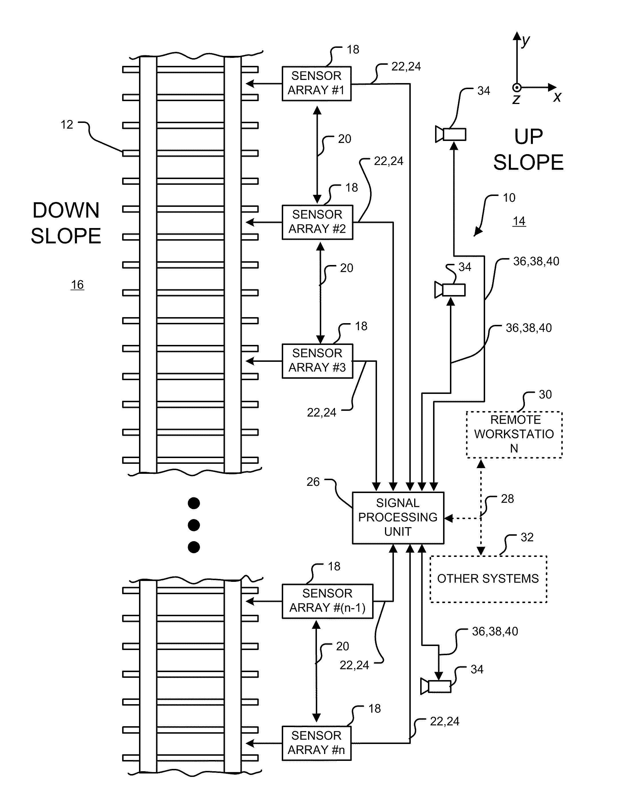
[0041]FIG. 1 is a schematic depiction of a rock fall detection system 10 according to a particular embodiment configured to detect rock fal...


PUM


Abstract

Aspects of the invention provide systems and methods for using ballast sensors to detect rock fall events in a vicinity of railway tracks or similar roadways or tracks. The ballast sensors are spaced apart from the tracks. Particular embodiments permit the use of signals from the ballast sensors to discriminate rock fall events from other types of events and to detect the hypocenter of a rock fall event.

Description

RELATED APPLICATIONS[0001]This application is a continuation in part of Patent Cooperation Treaty application No. PCT / CA2009 / 000837 filed 17 Jun. 2009, published under WO2010 / 003220 and entitled SYSTEM AND METHOD FOR DETECTING ROCK FALL. This application also claims the benefit of the priority of U.S. application No. 61 / 073,358 filed on 17 Jun. 2008 and entitled SEISMIC ROCK FALL DETECTION SYSTEM.TECHNICAL FIELD[0002]This invention relates to detection of rock fall events. Particular embodiments provide systems and methods for rock fall detection.BACKGROUND[0003]Rock fall events and other similar events (e.g. avalanches and washouts) which take place in a vicinity of railway tracks can damage the track, can damage passing trains and, in some cases, can derail passing trains which can in turn cause significant damage to the train and to people and / or property being transported by the train. Damaged trains can cause corresponding damage to the environment. Similar events which take pl...

Claims


Application Information

Patent Timeline
Patent Type & Authority Patents(United States)
IPC IPC(8): G01V1/28B61K9/08B61L23/04
CPCB61K9/08B61L23/041G01N29/44G01V1/001
Inventor NEDILKO, BOHDANWEIR-JONES, IAIN
Owner WEIR JONES ENG CONSULTANTS
Learn More