Method, apparatus, and system for evaluating video quality

a video quality and video frame technology, applied in the field of image quality evaluation, can solve the problems of affecting or damage the quality of video images restored by a receiving party from the received packet, and the difficulty of no-reference video quality evaluation to evaluate video quality, so as to improve the precision of evaluating and determine the quality of the video frame.

Inactive Publication Date: 2015-05-12
HUAWEI TECH CO LTD
View PDF9 Cites 4 Cited by
  • Summary
  • Abstract
  • Description
  • Claims
  • Application Information

AI Technical Summary

Benefits of technology

[0006]Embodiments provide a method, an apparatus, and a system for evaluating video quality, so as to improve the precision for evaluating the video quality.
[0019]In the embodiments, a method in the prior art that the video quality is determined only according to the number of lost packets and a packet loss rate is modified, and the locations of the most important lost packets is determined by analyzing the influence of the lost packet on other packets, and a damage degree or degree of intactness of the video frame is determined according to the most important lost packets, so as to determine the quality of the video frame. The method greatly improves the precision for evaluating the video quality.

Problems solved by technology

However, in transmission of a data packet, loss of a data packet, that is, a packet loss phenomenon, generally takes place; and sometimes, a packet delay phenomenon also takes place, and delay over video buffer is also interpreted as a packet loss phenomenon (because when a packet that is delayed over video buffer is received, a video receiving node generally does not process the packet, and packet loss processing introduced below also includes packet delay processing), causing that the quality of video images restored by a receiving party from the received packet is influenced or damaged.
In the implementation, the inventor finds through research that the method is effective in a case that the number of the packets in a slice is low, for example, in evaluation of standard-definition (standard-definition, SD) video quality; however, when the number of the packets in a slice is increased, the no-reference video quality evaluation is difficult to evaluate the video quality.

Method used


Image

  • Method, apparatus, and system for evaluating video quality
  • Method, apparatus, and system for evaluating video quality
  • Method, apparatus, and system for evaluating video quality

Examples


first embodiment

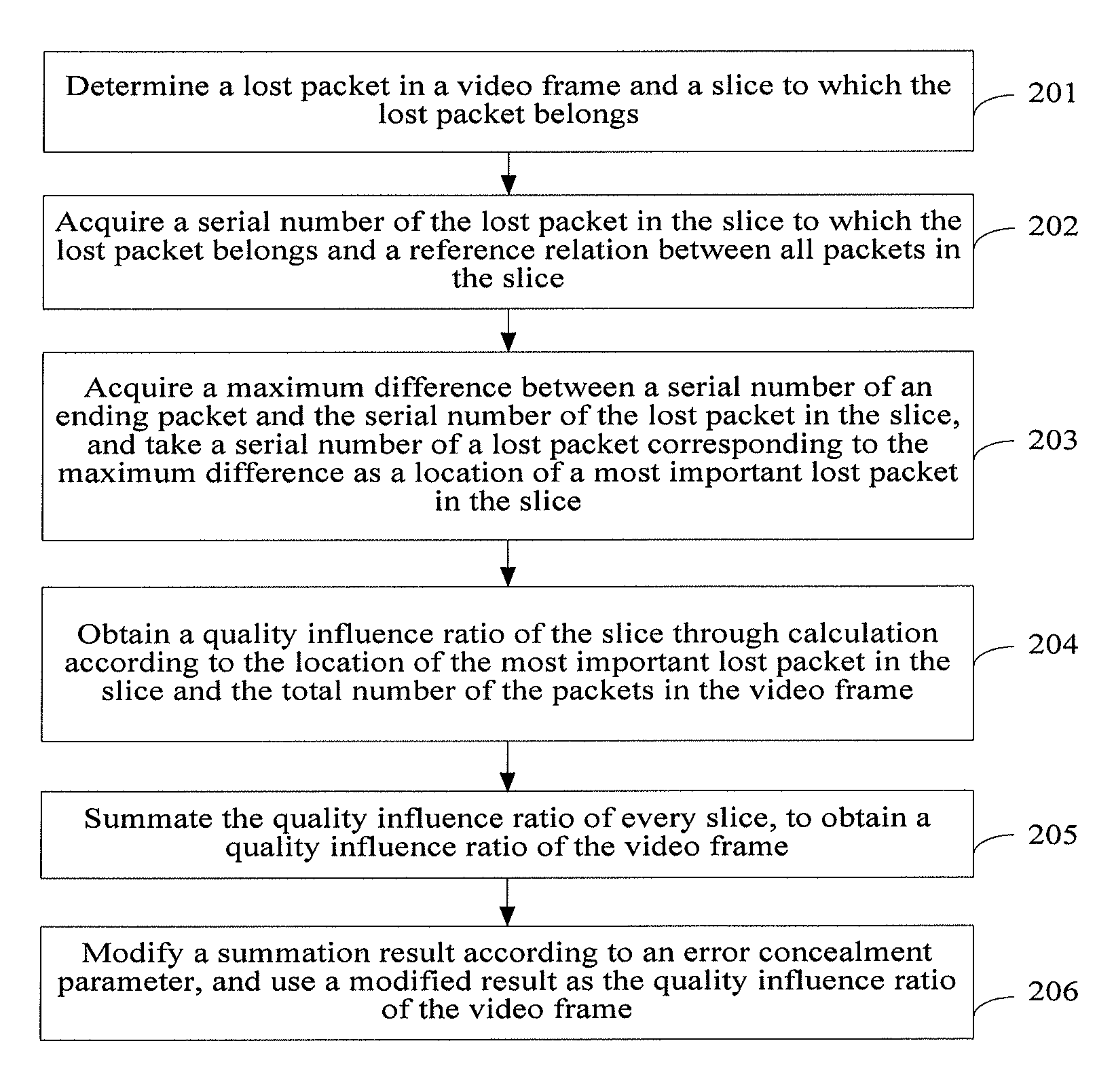
[0048]Referring to FIG. 2, it is a flow chart of a method according to a

[0049]The method may include:

[0050]Step 201: Determine a lost packet in a video frame and a slice to which the lost packet belongs.

[0051]The step is similar to step 101, and is not detailed again herein.

[0052]In this embodiment, the video frame includes n_Slices slices, n_Packets packets, a serial number of a starting packet in the whole video frame is seqNumStart, a serial number of an ending packet is seqNumEnd, a starting serial number of an ith slice is seqNumSliceStart_i, a serial number of an ending packet in the ith slice is seqNumSliceEnd_i, a range of serial numbers of packets in every slice is approximately seqNumStart to seqNumSliceEnd—1, seqNumSliceStart—2 to seqNumSliceEnd—2, . . . and seqNumSliceStart_(n_Slices) to seqNumEnd, respectively. The sequence includes a case in which data of an ending part of a slice and data of a starting part of a next slice are grouped into a same packet, and in this c...

second embodiment

[0075]Referring to FIG. 3, it is a flow chart of a method according to a

[0076]The embodiment shown in FIG. 3 may be applicable to a method for evaluating video quality in a case that location information of every slice in a video frame cannot be obtained (for example, the slice location information sent by a video transmission source is lost, or a starting packet or an ending packet of the slice is lost). The method may include:

[0077]Step 301: Estimate a location of every slice in a video frame.

[0078]For example, location information of slices may be obtained from a previous video frame and a next video frame, and the location of every slice in the current video frame, that is, a serial number of an ending packet or a serial number of a starting packet in every slice, may be estimated according to the location information. Because picture content in the previous video frame and picture content in the next video frame are usually similar, and the dividing of the slices may also be th...

third embodiment

[0096]Referring to FIG. 4, it is a flow chart of a method according to a

[0097]The method may include:

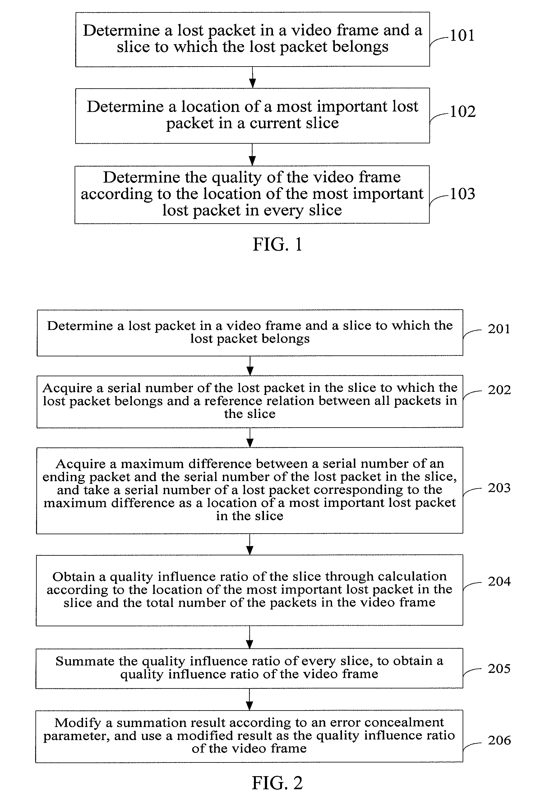
[0098]Step 401: Determine a lost packet in a video frame and a slice to which the lost packet belongs.

[0099]Step 402: Determine a location of a most important lost packet in a current slice.

[0100]Step 403: Determine the quality of the video frame according to the location of the most important lost packet in every slice.

[0101]Steps 401 to 403 are similar to the corresponding steps in the foregoing embodiments, and are not detailed again herein.

[0102]Step 404: Determine the quality (Quaitly_VideoSequence) of a video sequence according to the quality of the video frame and the number of video frames influenced by the video frame.

[0103]In this embodiment, for the whole video sequence formed by the current video frame and subsequent video frames, the quality of the video sequence may be represented by a quality influence ratio of the video sequence, and may be specifically obtained by mu...


PUM


Abstract

Embodiments of the present invention provide a method, an apparatus, and a system for evaluating video quality. In the embodiments of the present invention, a method in the prior art that the video quality is determined only according to the number of lost packets and a packet loss rate is modified, and the location of the most important lost packet is determined by analyzing the influence of the lost packet on other packets, and a damage degree or degree of intactness of the video frame is determined according to the most important lost packets, so as to determine the quality of the video frame. The method greatly improves the precision for evaluating the video quality.

Description

CROSS-REFERENCE TO RELATED APPLICATIONS[0001]This application is a continuation of International Application No. PCT / CN2010 / 077985, filed on Oct. 22, 2010, which claims priority to Chinese Patent Application No. 200910207416.X, filed on Nov. 3, 2009, both of which are hereby incorporated by reference in their entireties.FIELD OF THE APPLICATION[0002]The present application relates to the technical field of image quality evaluation, and in particular to a method, an apparatus, and a system for evaluating video quality.BACKGROUND OF THE APPLICATION[0003]With the rapid development of computer technology and communications technologies, remote transmission of video images becomes more and more convenient. An original video forms a video frame including a reference frame (for example, an IDR frame, an I frame, and a P frame) and a non-reference frame (a B frame, which is sometimes a reference frame) after video coding. One video frame generally includes one or more slices (slice), one sl...

Claims


Application Information

Patent Timeline
Patent Type & Authority Patents(United States)
IPC IPC(8): H04N17/00H04N19/89H04N19/154H04N19/169H04N19/172H04N19/174H04N21/442
CPCH04N17/004H04N21/44209H04N19/172H04N19/154H04N19/174H04N19/89H04N19/188
Inventor YANG, PEILINYU, WENXIAOXU, XIANGSHENGYANG, YOUQINGHU, YINLIANG
Owner HUAWEI TECH CO LTD
Why Eureka
Try Eureka