
Method and control unit for direct sampling of a plurality of radio bands

a technology of radio band and control unit, which is applied in the field of direct sampling of a plurality of radio bands, can solve the problems of further simplification of the overall system and greatly reduced signal bandwidth, and achieve the effects of reducing the overall system, simplifying the overall system, and facilitating sub-sampling

Active Publication Date: 2015-04-28
ROBERT BOSCH GMBH
View PDF10 Cites 0 Cited by
  • Summary
  • Abstract
  • Description
  • Claims
  • Application Information

AI Technical Summary

Benefits of technology

The present invention provides a method for processing different radio bands using a common sampling frequency. The method involves supplying different radio bands to an interface, which then processes them further using a signal processing unit. The method also includes steps to determine the common sampling frequency, which can be easily implemented in the HF preliminary stages. The technical effect of the invention is greater efficiency and simplification of the overall system, particularly for radio bands having different frequencies. A control unit is also provided to facilitate the implementation of the method.

Problems solved by technology

One disadvantage of this is that the bandwidth of the signal is greatly reduced for both FM / AM and DAB before digitizing the bandwidth of the signal, so that for receiving two or more signals, each of which may correspond to one transmitter, a complete receiver path including a tuner module and an A / D converter is necessary for each signal to be received.
This may lead to a further simplification of the overall system.

Method used


Image

  • Method and control unit for direct sampling of a plurality of radio bands
  • Method and control unit for direct sampling of a plurality of radio bands
  • Method and control unit for direct sampling of a plurality of radio bands

Examples


Embodiment Construction

[0028]In the following description of preferred exemplary embodiments of the present invention, the same or similar reference numerals are used for the elements which are shown in the various figures and have similar effects, so that a repeated description of these elements is omitted.

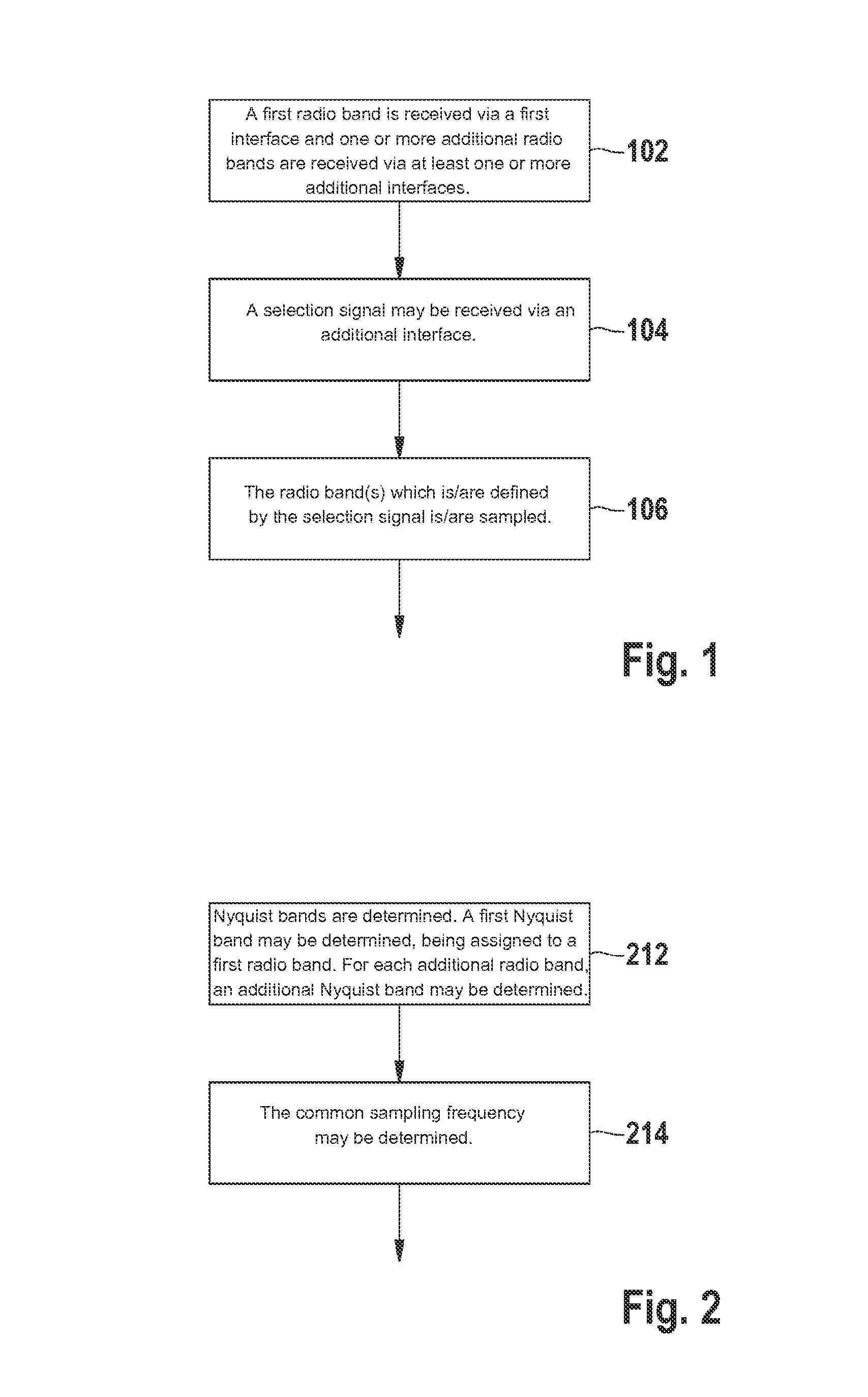
[0029]FIG. 1 shows a flow chart of a method according to the present invention for direct sampling of a plurality of radio bands according to an exemplary embodiment of the present invention.

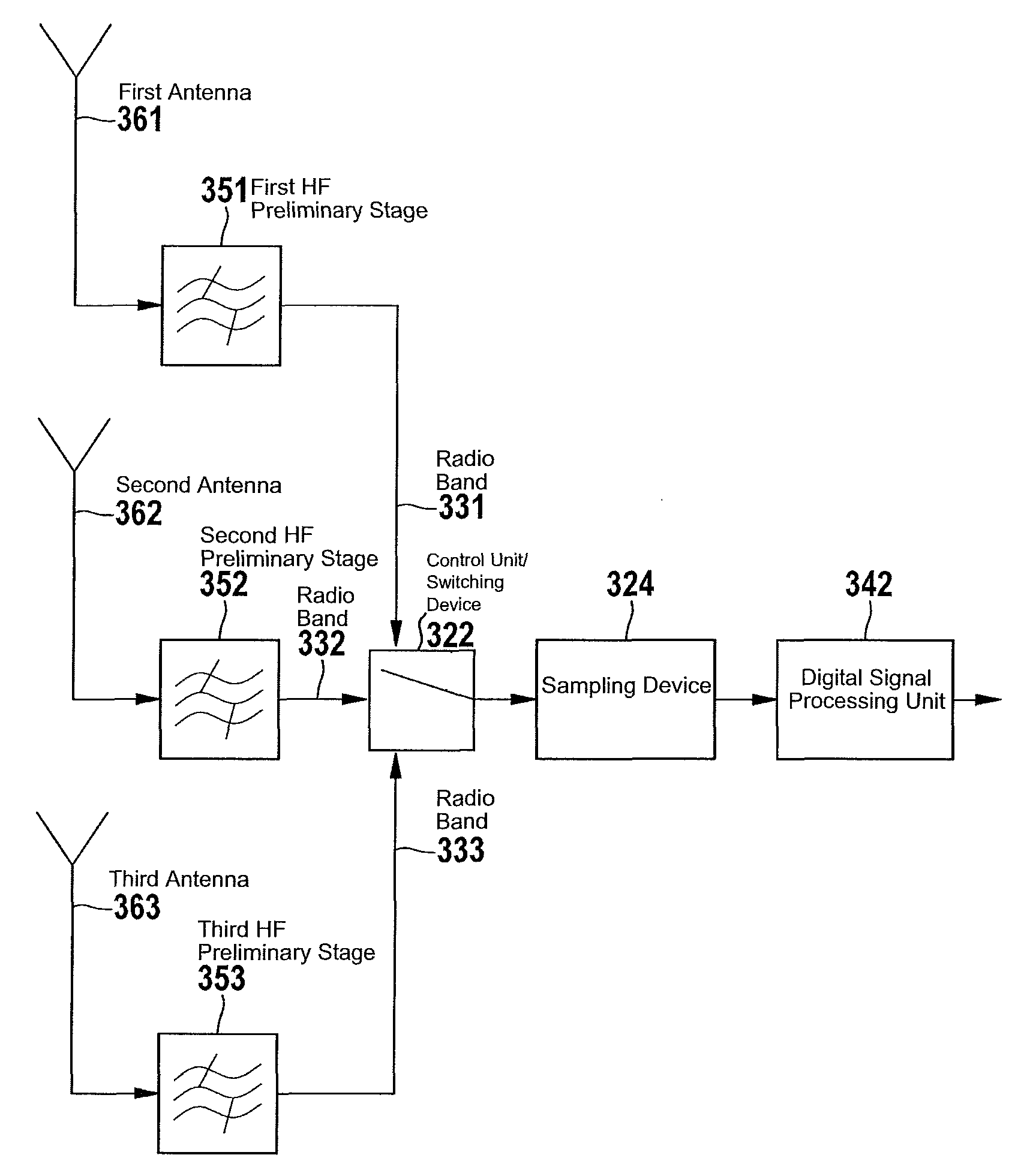
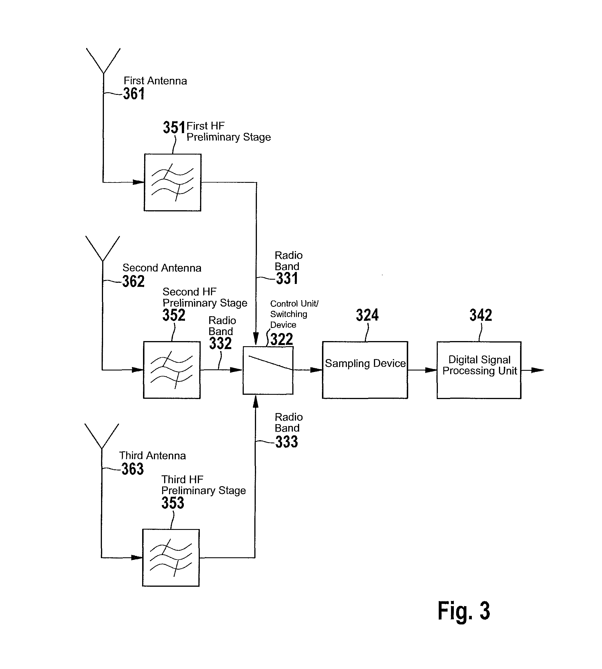
[0030]In a first step, a first radio band is received 102 via a first interface and one or more additional radio bands are received via at least one or more additional interfaces. For example, a first radio band may be received via a first interface, a second radio band may be received via a second interface and a third radio band may be received via a third interface. According to this exemplary embodiment, the radio bands have different frequency ranges. In another step a selection signal may be received 104 via ...


PUM


Abstract

A method for direct sampling of a plurality of radio bands, including a step of receiving a first radio band via a first interface and at least one additional radio band via at least one additional interface, the first radio band and the at least one additional radio band each being associated with different frequency ranges, and the first radio band or the at least one additional radio band being a DAB band. Furthermore, a selection signal is received via an interface, the selection signal indicating whether further processing of the first radio band and / or the at least one additional radio band takes place. Depending on the selection signal, the first radio band is sampled at a common sampling frequency and / or the at least one additional radio band is sampled at the common sampling frequency.

Description

FIELD OF THE INVENTION[0001]The present invention relates to a method for, direct sampling of a plurality of radio bands, a method for determining a common sampling frequency, a control unit, and a computer program product.BACKGROUND INFORMATION[0002]DAB (Digital Audio Broadcasting) is a digital transmission standard in particular for radio programs. The term DAB is used below as an umbrella term for DAB, DAB+ and DMB (Digital Media Broadcasting).[0003]Current DAB, FM and AM radio receivers have tuner modules (receiver modules) in which the HF signals (high-frequency signals) coming from the antenna are filtered, amplified and mixed to obtain a suitable intermediate frequency. In some receiver systems, the signals are then digitized using A / D converters (analog-digital converters) and are digitally demodulated. Separate tuner modules for DAB and FM / AM are used for this purpose.[0004]One disadvantage of this is that the bandwidth of the signal is greatly reduced for both FM / AM and DA...

Claims


Application Information

Patent Timeline
Patent Type & Authority Patents(United States)
IPC IPC(8): H04B7/00H04B1/00H04H40/27
CPCH04B1/0064H04H40/27H04H2201/11H04H2201/12H04H2201/20
Inventor LEHR, CARSTENNYENHUIS, DETLEVRISSE, MARCUS
Owner ROBERT BOSCH GMBH
Learn More