
Backlight unit comprising a sheet guide having an opening surrounding edges of a bottom cover, light sources, and a light source fixing unit and liquid crystal display device using the same

a backlight unit and sheet guide technology, applied in the field of backlight units, can solve the problems of lowering product reliability, unable to prevent optical defects generated, and defect in image display

Active Publication Date: 2015-04-21
LG DISPLAY CO LTD
View PDF12 Cites 1 Cited by
  • Summary
  • Abstract
  • Description
  • Claims
  • Application Information

AI Technical Summary

Benefits of technology

The design effectively prevents optical defects like light leakage, allowing for a minimized bezel thickness while maintaining image quality and enhancing product reliability.

Problems solved by technology

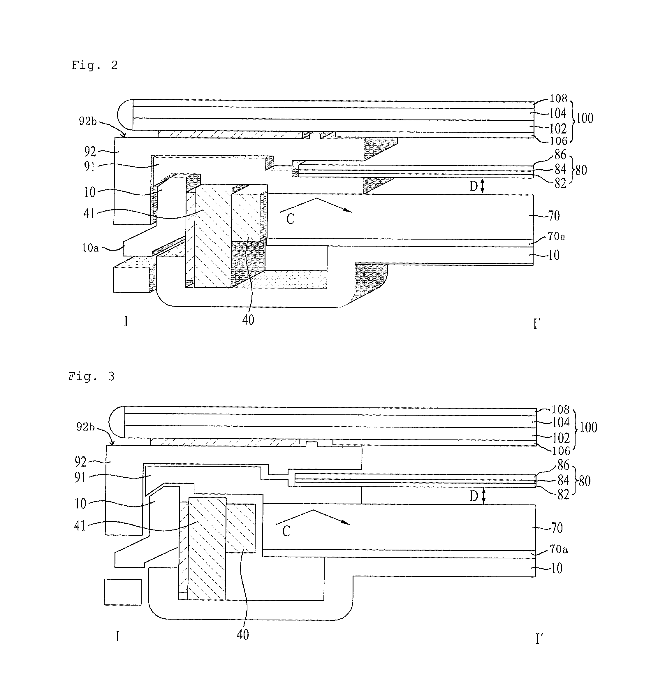
However, if the thin bezel is formed, a distance between the plural light sources and the diffusion plate is inevitably narrowed, and thus it may be impossible to prevent optical defects generated by the shape of diffusion sheets when the diffusion sheets are disposed directly on the diffusion plate.
Particularly, when the sufficient distance between the respective light sources and the diffusion plate is not obtained due to the thin bezel, optical defects such as light beams or light leakage due to the rib shape of the prism sheet from among the diffusion sheets occur, thereby causing a defect in image display and greatly lowering product reliability.
Thereby, when optical sheets are disposed directly on the diffusion plate, optical defects cannot be prevented by the shape of the diffusion sheets.
Particularly, when the distance between respective light sources and the diffusion plate is not sufficiently secured by reducing the thickness of the bezel, optical defects due to the rib shape of the prism sheet from among the diffusion sheets occur and thus cause image display defects.

Method used


Image

  • Backlight unit comprising a sheet guide having an opening surrounding edges of a bottom cover, light sources, and a light source fixing unit and liquid crystal display device using the same
  • Backlight unit comprising a sheet guide having an opening surrounding edges of a bottom cover, light sources, and a light source fixing unit and liquid crystal display device using the same
  • Backlight unit comprising a sheet guide having an opening surrounding edges of a bottom cover, light sources, and a light source fixing unit and liquid crystal display device using the same

Examples


Embodiment Construction

[0020]Reference will now be made in detail to the preferred embodiments of the present invention, examples of which are illustrated in the accompanying drawings. Wherever possible, the same reference numbers will be used throughout the drawings to refer to the same or like parts.

[0021]Hereinafter, a backlight unit and a liquid crystal display device using the same in accordance with one embodiment of the present invention will be described in more detail with reference to the accompanying drawings.

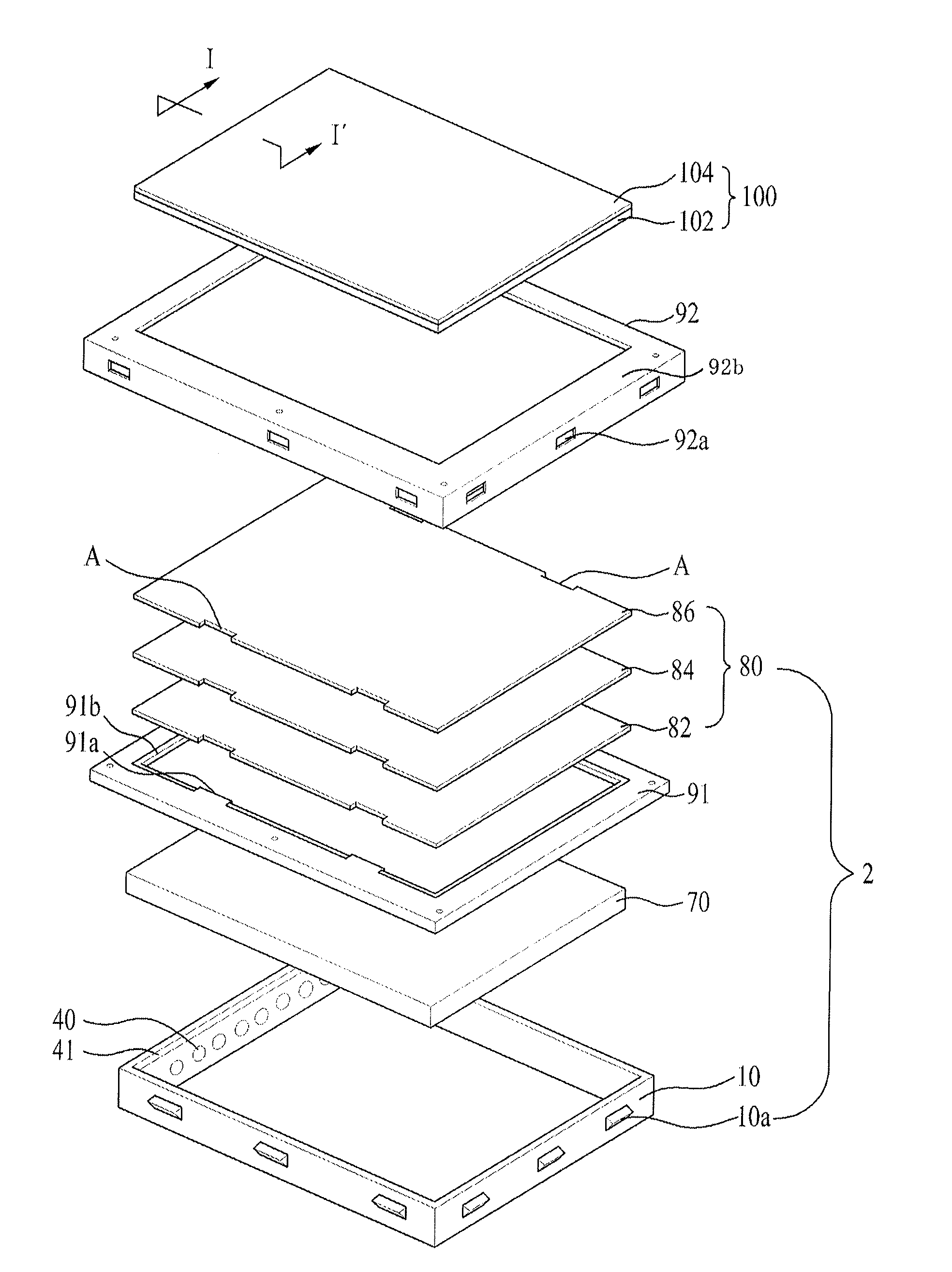
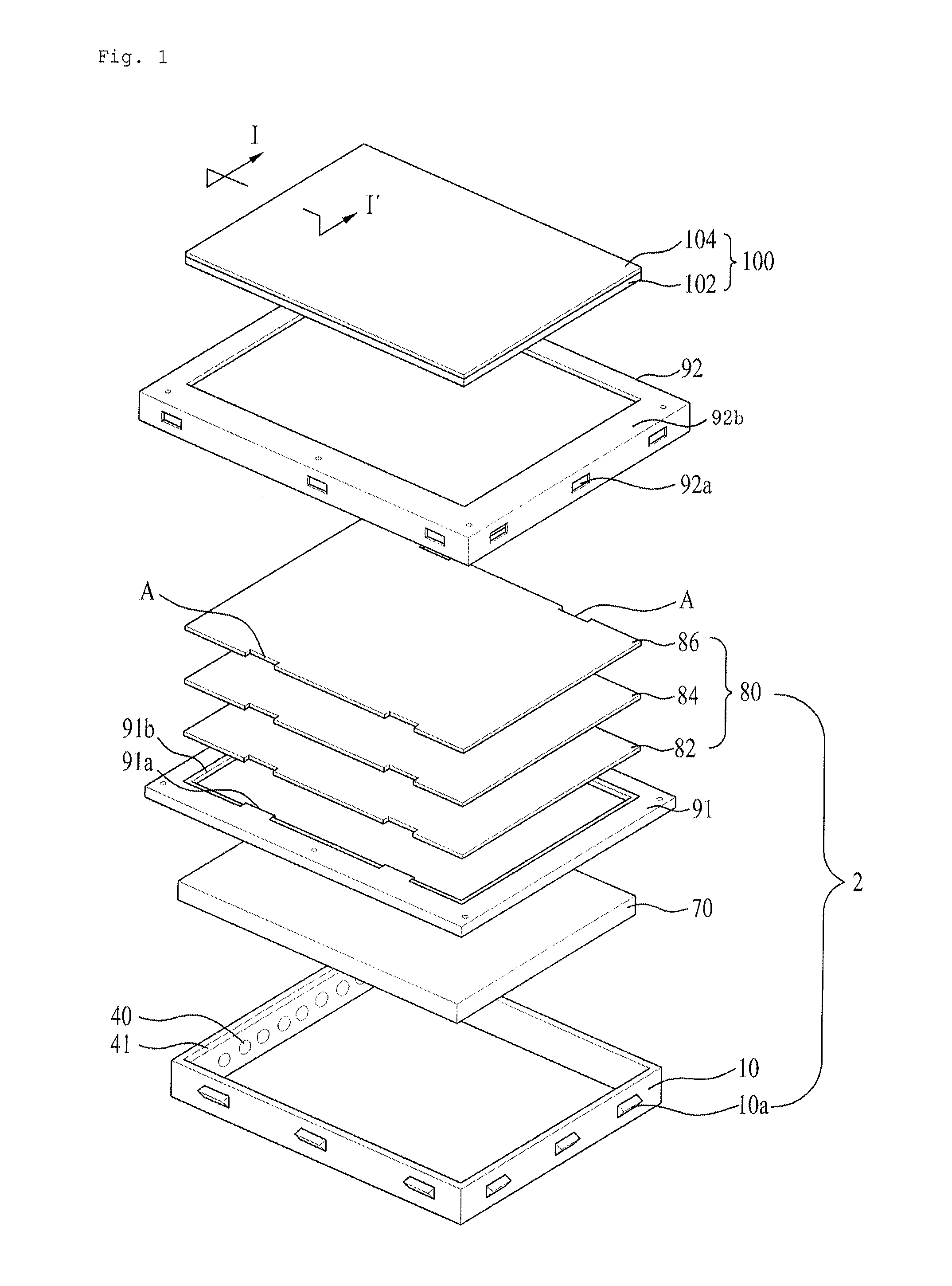
[0022]FIG. 1 is an exploded perspective view schematically illustrating a backlight unit and a liquid crystal display device using the same in accordance with one embodiment of the present invention. Here, in the following, basically, the wording “front surface” of an element indicates the surface of the element at the side of a liquid crystal panel 100 in a direction from a bottom cover 10 to the liquid crystal display panel 100 in an assembled state of the liquid crystal display device; ...


PUM

PropertyMeasurementUnit
thicknessaaaaaaaaaa
widthaaaaaaaaaa
sizeaaaaaaaaaa

Abstract

Disclosed are a backlight unit, an assembly structure of which is modified to minimize the thickness of a bezel and to prevent optical defects, such as light leakage, and a liquid crystal display device using the backlight unit. The liquid crystal display device includes a liquid crystal panel, at least one light source fixing unit on which plural light sources are mounted and which is fixed to the inner side surface of a bottom cover, a diffusion plate receiving light from the plural light sources through a light entry plane and changing the progress direction of light into a forward direction, a sheet guide formed on the front surface of the bottom cover in a shape in which the inside of the sheet guide is opened, and plural optical sheets disposed on the sheet guide and separated from the diffusion plate to perpendicularly emit light from the diffusion plate.

Description

[0001]This application claims the benefit of Korean Patent Application No. 10-2012-0022839, filed on Mar. 6, 2012, which is hereby incorporated by reference as if fully set forth herein.BACKGROUND[0002]1. Field of the Disclosure[0003]The present disclosure relates to a backlight unit, an assembly structure of which is modified to minimize the thickness of a bezel forming the external appearance of a liquid crystal display device and to prevent optical defects, such as light leakage, and a liquid crystal display device using the backlight unit.[0004]2. Discussion of the Related Art[0005]Recently, as flat panel display devices used in personal computers, portable terminals and monitors of various information equipment, liquid crystal display devices, plasma display devices, field emission display devices and light emitting display devices are on the rise.[0006]In such a flat panel display device, a display panel displaying an image is seated on a separate guide bracket or panel guide,...

Claims


Application Information

Patent Timeline
Patent Type & Authority Patents(United States)
IPC IPC(8): G02F1/1333G02F1/1335F21V8/00
CPCG02B6/0011G02F1/133606G02F1/133308G02B6/0088G02B6/009G02F2001/133317G02F2001/133322G02F1/133317G02F1/133322G02F1/1333G02F1/1335
Inventor JEON, HYEON-KUPARK, YONG-SHIN
Owner LG DISPLAY CO LTD
Learn More