
Apparatus for sectioning an electric energy flow in one or more conductors, and an electric energy generating plant comprising said apparatus

a technology of electric energy flow and electric energy generating plant, which is applied in the direction of electrical apparatus, dc network circuit arrangement, substation/switching arrangement details, etc., can solve the problems of not offering sufficient strength and longevity, unable to ensure the possibility of sectioning under load and not, and unable to meet the requirements of safety conditions

Inactive Publication Date: 2015-04-21
ENERGY GLOBAL GREEN SOLUTIONS S R L IN FORMA ABBR
View PDF8 Cites 1 Cited by
  • Summary
  • Abstract
  • Description
  • Claims
  • Application Information

AI Technical Summary

Benefits of technology

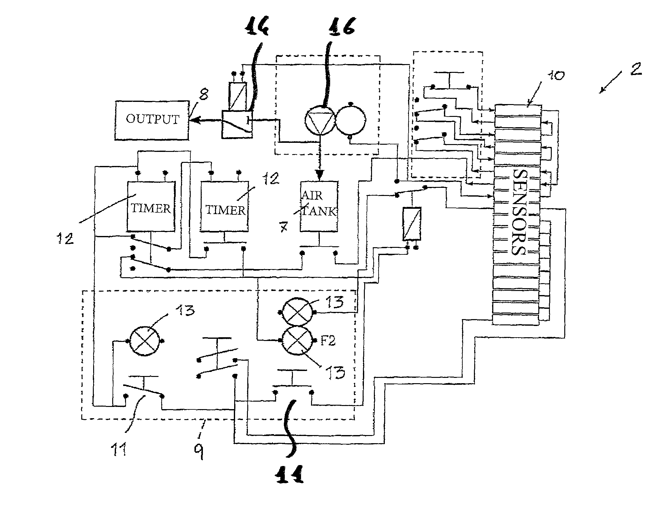
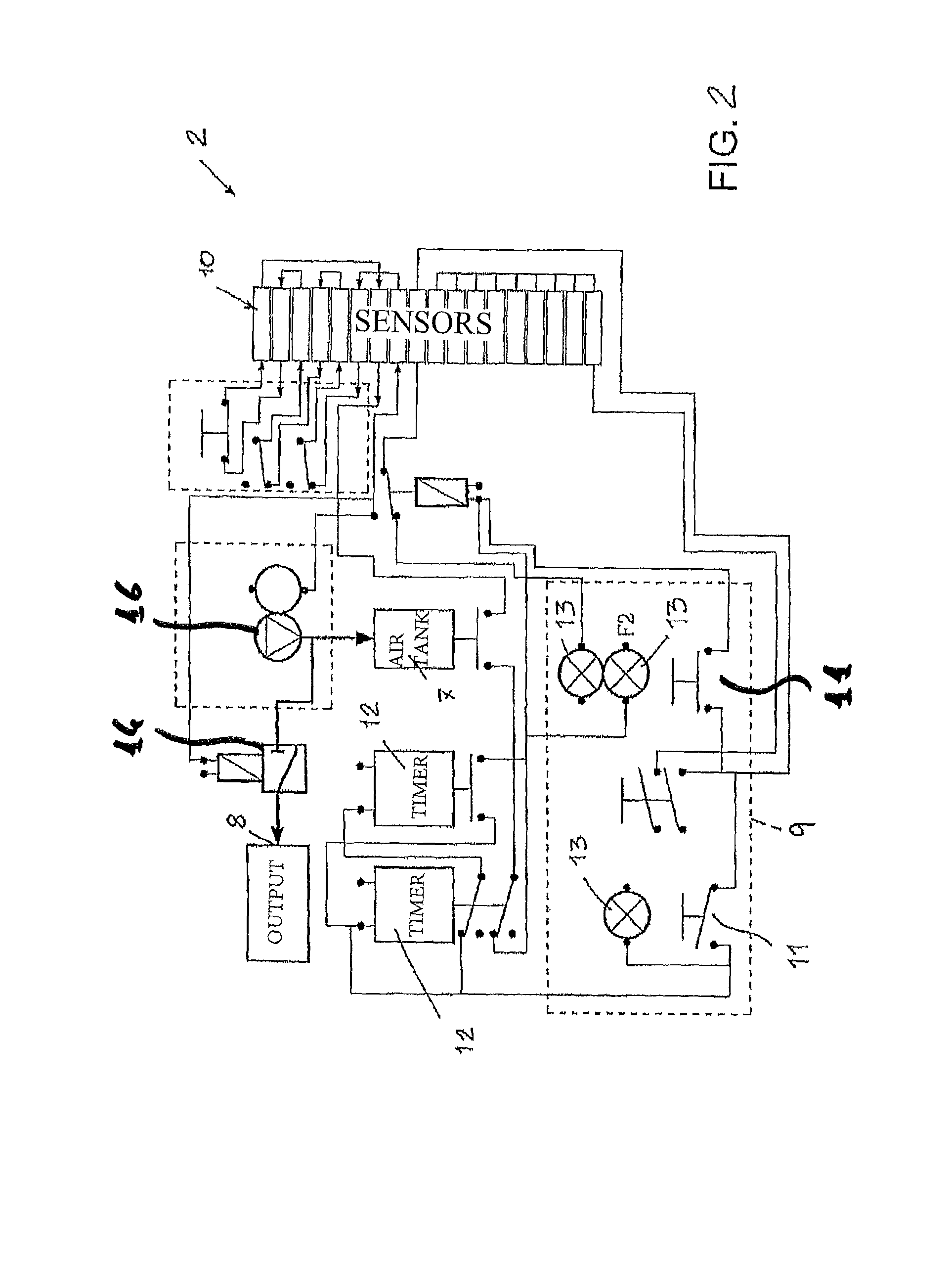
[0028]A further object of the invention is that of making an apparatus that makes it possible to carry out the interruption of the electric current with a manoeuvre that is either manual or automated, for example controlled by smoke sensors, temperature sensors, and other safety apparatuses.
[0029]The present apparatus, thanks to its special constructional features, is able to ensure high guarantees of reliability and of safety.

Problems solved by technology

As known, in electric energy plants comprising a plurality of generators connected in series (like for example batteries, accumulators, photovoltaic panels or similar) it is sometimes difficult to ensure the possibility of sectioning under load and not.
In many cases, for example in photovoltaic plants, the connections between the apparatuses are made with terminals and cable lugs clamped by means of screws, without the interposition of magnetic remote switches, since the latter do not offer sufficient guarantee of strength and longevity, in high-burden applications.
The safety conditions could only be attained with the addition of airtight containers, high quality insulating materials and other provisions that would make the plant very expensive.
Such an operation is clearly very dangerous or impossible in the case of fire or when humidity is present.
It has already been found that during fires, in photovoltaic arrays installed on industrial buildings, teams of fire-fighters have not been able to intervene on the roofs with hoses because the live photovoltaic arrays, through the water, would have discharged the electrical energy into the pumping devices and particularly onto the people in contact with such equipment, with lethal consequences due to the high voltages of the plants.
It is therefore only possible to intervene to put out these fires with powders, which, however, over large surfaces like those of industrial buildings, are not suitable for reasons of volume and technical application difficulties.
Even foams, for the same reasons as water, cannot be used to extinguish fires in the presence of live plants.
Therefore, any photovoltaic plant, even the smallest one, greatly exceeds the voltage and current values considered harmless.
Another problem of known photovoltaic plants, operating for many years, lies in that the insulation systems may no longer be adequate and possible dispersions could endanger the safety of people that have to work on roofs for normal maintenance operations.
In other words, existing plants may be dangerous even without exceptional circumstances, such as a fire.

Method used


Image

  • Apparatus for sectioning an electric energy flow in one or more conductors, and an electric energy generating plant comprising said apparatus
  • Apparatus for sectioning an electric energy flow in one or more conductors, and an electric energy generating plant comprising said apparatus
  • Apparatus for sectioning an electric energy flow in one or more conductors, and an electric energy generating plant comprising said apparatus

Examples


Embodiment Construction

[0057]Referring to FIG. 3, the apparatus for sectioning an electric energy flow in one or more conductors, according to the invention, globally indicated with reference numeral 1, comprises a control unit (or board) 2, connected to a compressed air source 3 and from which pipes branch off that define a pneumatic circuit 4, which reaches respective pneumatic remote switch devices 5.

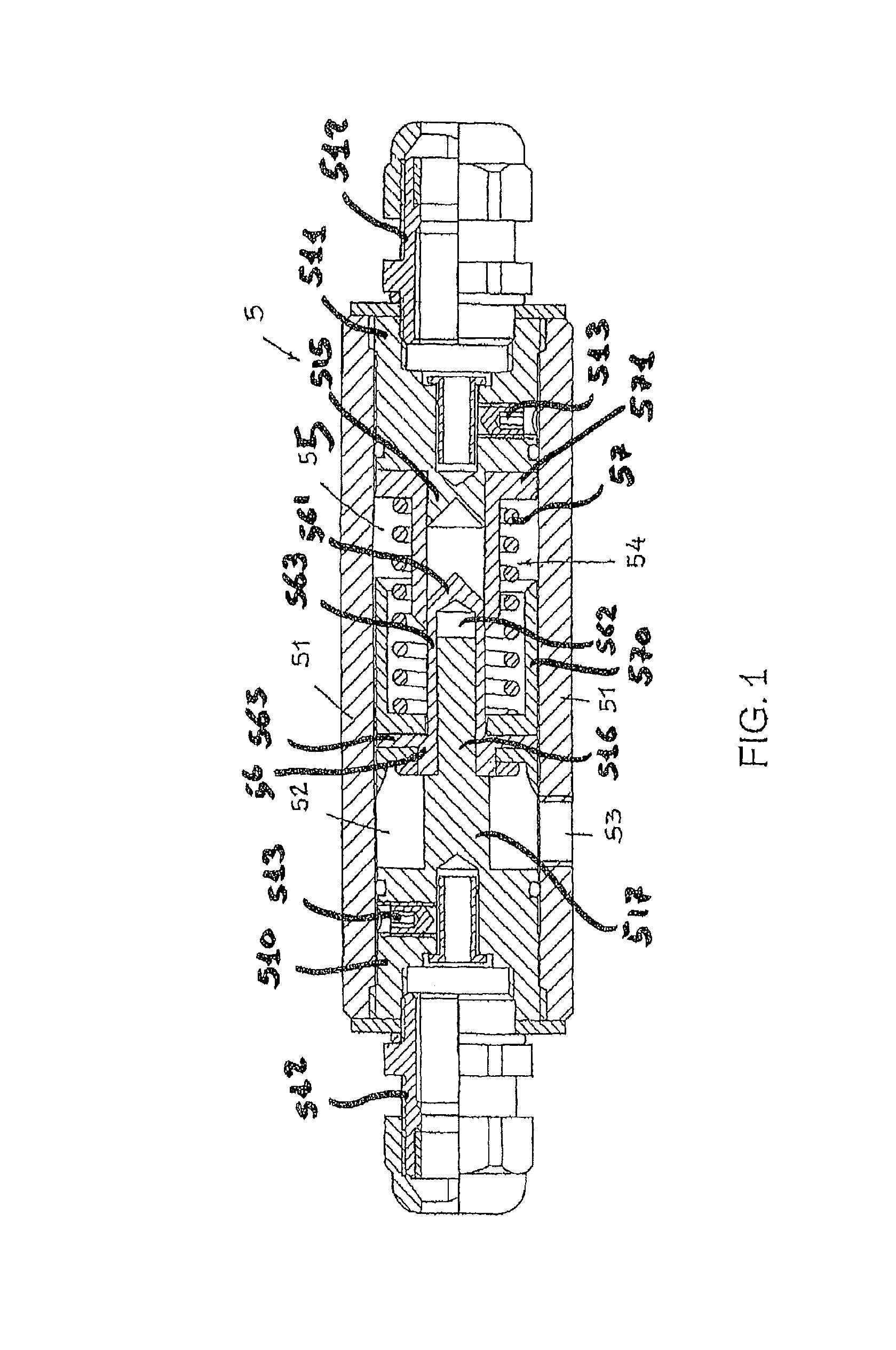
[0058]Now referring to FIGS. 1, 4 and 5, each pneumatic remote switch 5 comprises a casing 51 made from plastic material (preferably rigid Nylon), which defines a first chamber 52, fed through an input 53 connected to the pneumatic circuit 4 seen in FIG. 3

[0059]A spring mechanism 54 keeps the electrical contacts closed when the first chamber 52 is under pressure.

[0060]If pressure fails, due to an interruption in power supply or due to a tearing of the casing 51, the spring mechanism 54 disconnects the electrical contacts.

[0061]The pneumatic remote switch 5 thus represents a normally open contact, which is ...


PUM


Abstract

The present application describes an apparatus (1) for sectioning an electric energy flow in one or more conductors (15) of an electric energy generating plant (100), comprising a pneumatic circuit (4) that feeds a plurality of pneumatic remote switches (5), and a control unit (2) that controls such a pneumatic circuit (4); the pneumatic remote switches (5) intercept conductors (15) of an electric energy generating plant (100) and are able to interrupt the passage of current both for automatic safety intervention and for manual or automatic controlled intervention; it also describes an electric energy generating plant (100) comprising a plurality of electrical generators (6) connected in series and the aforementioned sectioning apparatus (1), the pneumatic remote switches (5) of which intercept at least one conductor (15) of such a plurality of electrical generators (6).

Description

[0001]This application is a national phase of PCT / IT2012 / 001399, filed May 7, 2012, and claims priority to MI2011A001057, filed Jun. 13, 2011, the entire contents of all of which are hereby incorporated by reference.DESCRIPTION[0002]1. Field of Application[0003]The present invention concerns an apparatus for sectioning an electric energy flow in one or more conductors, as well as an electric energy generating plant comprising said apparatus.[0004]2. Prior Art[0005]As known, in electric energy plants comprising a plurality of generators connected in series (like for example batteries, accumulators, photovoltaic panels or similar) it is sometimes difficult to ensure the possibility of sectioning under load and not.[0006]In many cases, for example in photovoltaic plants, the connections between the apparatuses are made with terminals and cable lugs clamped by means of screws, without the interposition of magnetic remote switches, since the latter do not offer sufficient guarantee of st...

Claims


Application Information

Patent Timeline
Patent Type & Authority Patents(United States)
IPC IPC(8): H02J1/00H01H35/24H01H35/38
CPCH01H35/38H01H35/24H01H2300/04
Inventor OLDANI, RENZONOLLI, CLAUDIO
Owner ENERGY GLOBAL GREEN SOLUTIONS S R L IN FORMA ABBR
Learn More