Closed loop tracking system using signal beam

a closed loop and tracking system technology, applied in the field of solar tracking systems, can solve the problems of affecting the performance of the heliostat, pointing inaccuracy, and simple approach is impractical, and achieve the effect of avoiding the problem of overwhelming the positioning sensor

Active Publication Date: 2015-04-21
HELIOGEN HLDG INC
View PDF18 Cites 31 Cited by
  • Summary
  • Abstract
  • Description
  • Claims
  • Application Information

AI Technical Summary

Benefits of technology

The patent describes a system that improves the efficiency of a heliostat array by running it at higher efficiency without having to take one or more mirrors to a non-operative location for calibration. The system is also able to calibrate and control in an "on sun mode," which results in higher accuracy.

Problems solved by technology

These heliostat arrays generally contain many thousands of mirrors, and maintaining alignment of these mirrors over time towards the central receiver is a problem that is regularly encountered.
One problem that negatively impacts heliostat performance is the problem of directing the reflected sunlight from the various heliostat mirrors onto the same desired region of focus on the central receiver throughout the day, and throughout the year.
Given that the heliostat mirrors may be located some distance away from the central receiver, even minor errors in mirror orientation can cause the reflected sunlight to miss the receiver, thereby causing the heliostat array as a whole to function with suboptimal efficiency.
Although heliostat mirrors are usually controlled by calibrated actuators, the calibration of the actuators may drift with time, causing pointing inaccuracies.
In practice, however, this simple approach is impractical given that as the number of heliostat mirrors increases, the large amount of light and heat on the central receiver will tend to overwhelm (destroy or blind) any sensors placed near the beam focus.
However using the man beam from even one off sun oriented heliostat can be problematic because the high intensity of even one main beam can still tend to overwhelm optical sensors and digital cameras, resulting in lower accuracy, and additionally, the off sun mode of the heliostat is at best a surrogate for the heliostat's setting in the on-sun mode.

Method used


Image

  • Closed loop tracking system using signal beam
  • Closed loop tracking system using signal beam
  • Closed loop tracking system using signal beam

Examples


Embodiment Construction

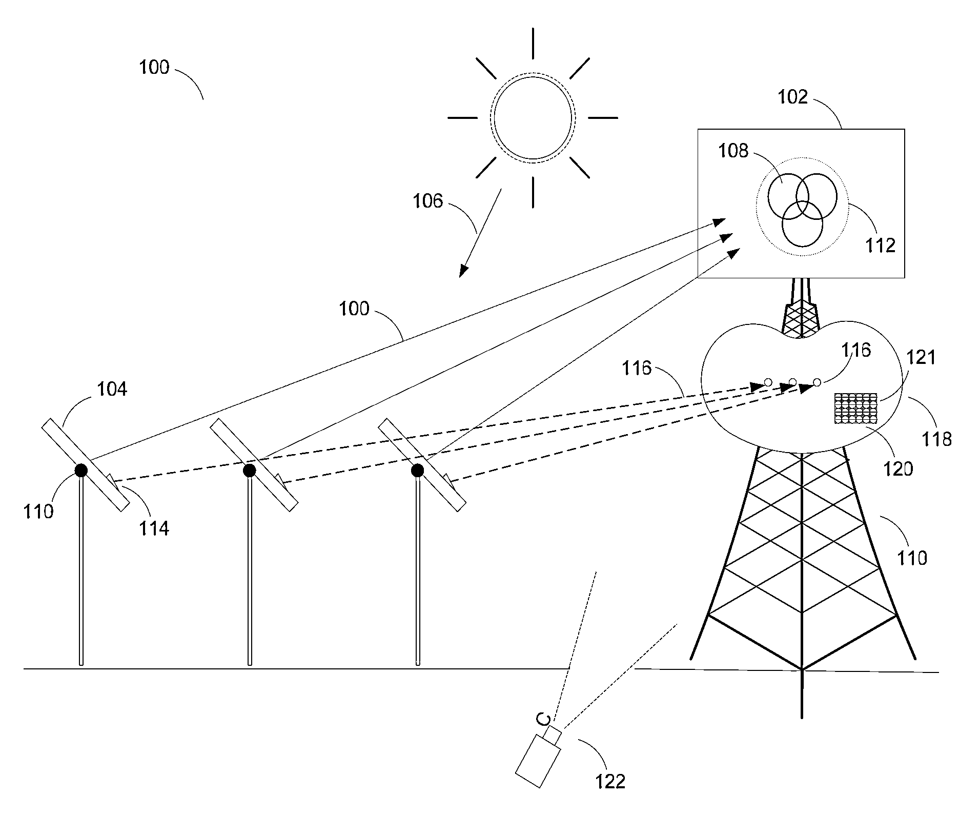
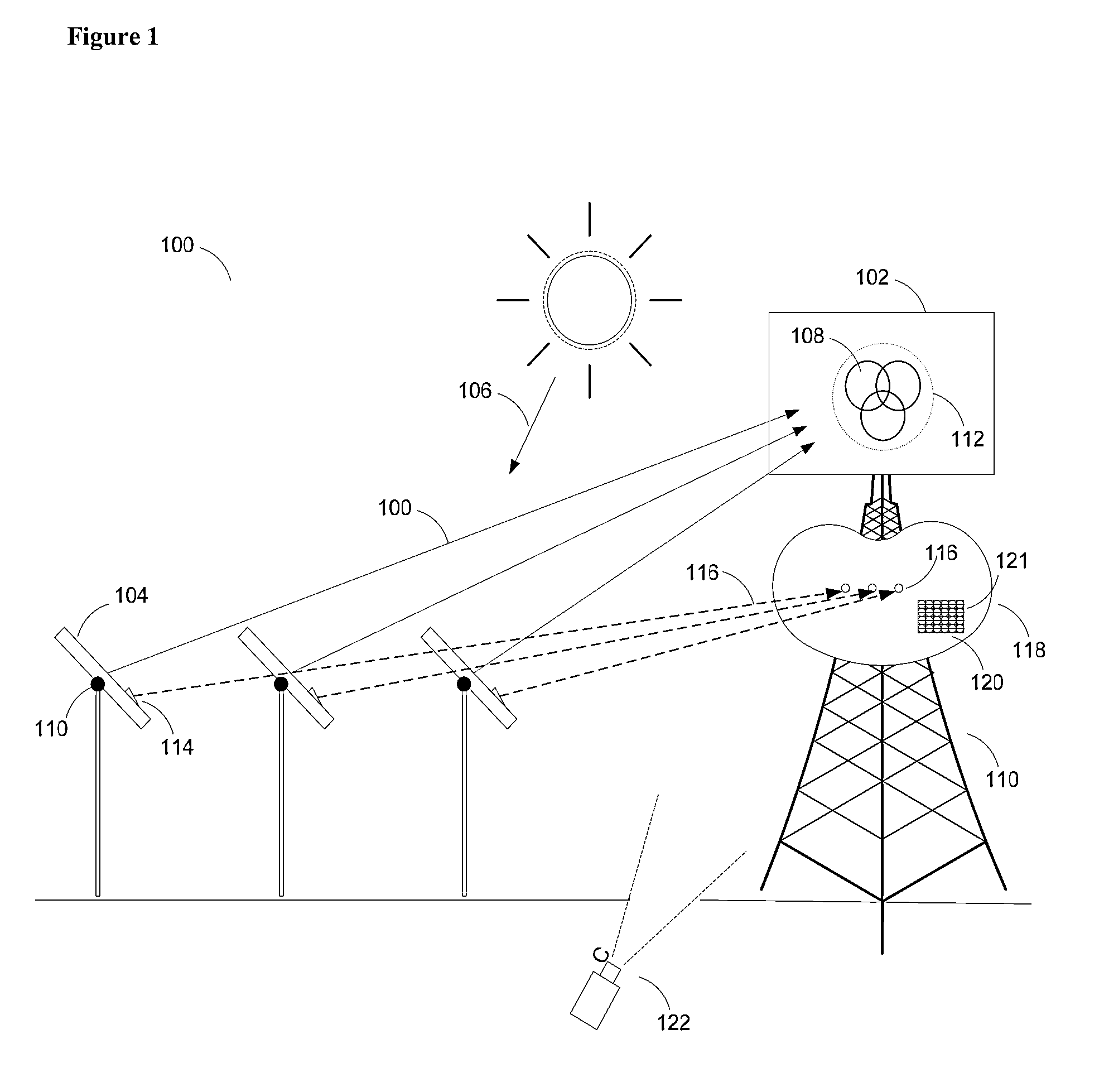
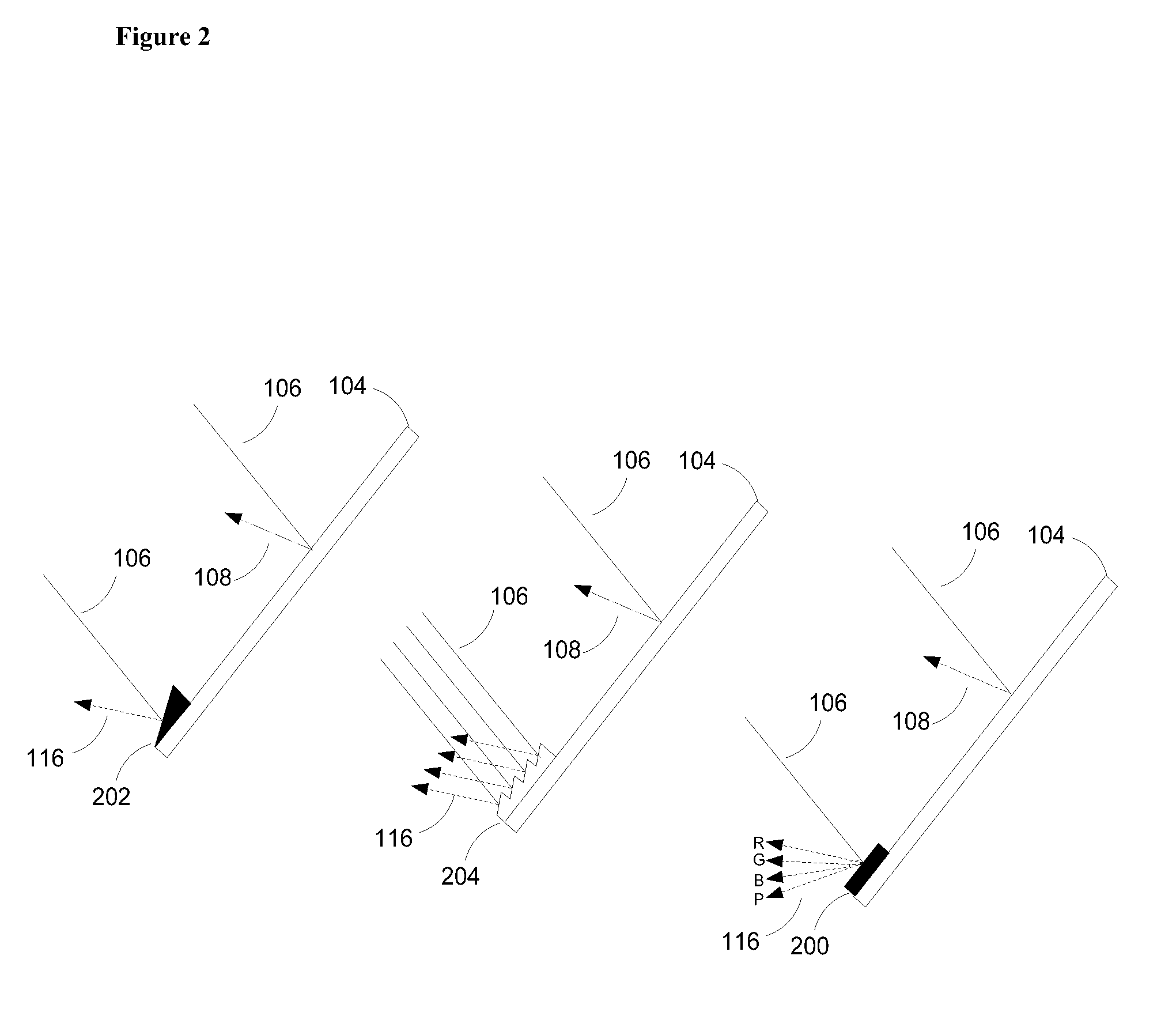
[0026]At the most general level, one or more embodiments of the invention are directed towards a system and method for positioning a heliostat mirror within an array of heliostat mirrors so that a main beam of incident sunlight reflected from said heliostat mirror converges onto a single region of a receiver. The system and method is implemented in accordance with one or more embodiments of the invention as a closed loop feedback system and method, but it can be used in an open loop manner if this is desired. In the following description, numerous specific details are set forth in order to provide a more thorough understanding of embodiments of the invention. It will be apparent, however, to an artisan of ordinary skill that the present invention may be practiced without incorporating all aspects of the specific details described herein. In other instances, specific features, quantities, or measurements well known to those of ordinary skill in the art have not been described in deta...


PUM


Abstract

The invention is a system and method for heliostat mirror control. Here, each heliostat mirror generates a low intensity “signal beam”, directed at an angle off from the heliostat mirror's high intensity and sensor blinding “main beam” of reflected solar energy. The low intensity signal beams may be created by reflecting a small portion of the incident solar light at an angle from the main beam, by reflected artificial light, or from lasers shinning onto mirrors from known locations. The signal beams are detected by optical sensors mounted way from the main heliostat receiver focus, and can be used in a closed loop control system to efficiently ensure that individual heliostat mirrors in a heliostat array accurately track sunlight and direct the sunlight to a central receiver. Because heliostat mirrors need not be taken “off sun” for positioning, the system allows heliostat arrays to be run at high efficiency.

Description

[0001]This application claims the benefit of U.S. Provisional Patent Application 61 / 132,794, filed Jun. 20, 2008, the specification of which is hereby incorporated herein by reference.BACKGROUND OF THE INVENTION[0002]1. Field of the Invention[0003]One or more embodiments of the invention are directed to the field of solar tracking systems. More particularly, but not by way of limitation, embodiments of the invention provide systems and methods for keeping an array of heliostat mirrors properly oriented towards a solar receiver.[0004]2. Description of the Related Art[0005]As world oil supplies dwindle, and demand for energy increases, heliostats and other mirror based solar collection devices are becoming a widely utilized method of energy production. A heliostat is a stationary device that tracks the movement of the sun. The heliostat typically contains a mirror that is oriented throughout the day to redirect sunlight towards a receiver. In large-scale solar energy installations, an...

Claims


Application Information

Patent Timeline
IPC IPC(8): F24J2/38F24J2/34F24J2/36F24S50/20
CPCF24J2/36Y02E10/47F24S50/20F24S2050/25F24S23/77G01S3/7803G01S3/7861
Inventor GROSS, WILLIAM
Owner HELIOGEN HLDG INC
Why Eureka
Try Eureka