
Lens device

a technology of lens and frame, which is applied in the direction of spectacles/goggles, instruments, spectacles/goggles, etc., can solve the problems of lens or frame being easily broken, lens or frame being hard to press, and easy to be scratched, so as to prevent damage, prolong the service life, and improve the usability and lifespan of the product.

Inactive Publication Date: 2015-04-14
HWA MEEI OPTICAL
View PDF5 Cites 8 Cited by
  • Summary
  • Abstract
  • Description
  • Claims
  • Application Information

AI Technical Summary

Benefits of technology

[0005]In view of the foregoing subject, an objective is to provide a lens device whose lens is easily fixed, and thereby the usability and lifespan of the product can be increased.
[0017]As mentioned above, the fastener of the lens device according to this invention is disposed pivotally to the frame and is rotatable in relation to the frame. When the fastener rotates so that the hook portion enters into the indentation of the lens, the supporting surface of the fastener can press against a side of the indentation for fixing the lens. Thereby, either the assembly or disassembly, the lens doesn't need to be pushed hard into the slot of the frame (as the prior art) so that the lens can be prevented from being damaged. Furthermore, the lens of the lens device of the invention is very easy to be fixed, and thereby the usability and lifespan of the product can be increased and enhanced. Besides, with the convenient assembly and disassembly of the invention, the user can easily replace the lens.

Problems solved by technology

In this case, however, the lens needs to be hard pressed into the slot to be fixed to the frame although the frame is a little flexible.
In addition, the user's improper assembling might cause the lens or frame to be broken or easily scratched.

Method used


Image

  • Lens device
  • Lens device
  • Lens device

Examples


Embodiment Construction

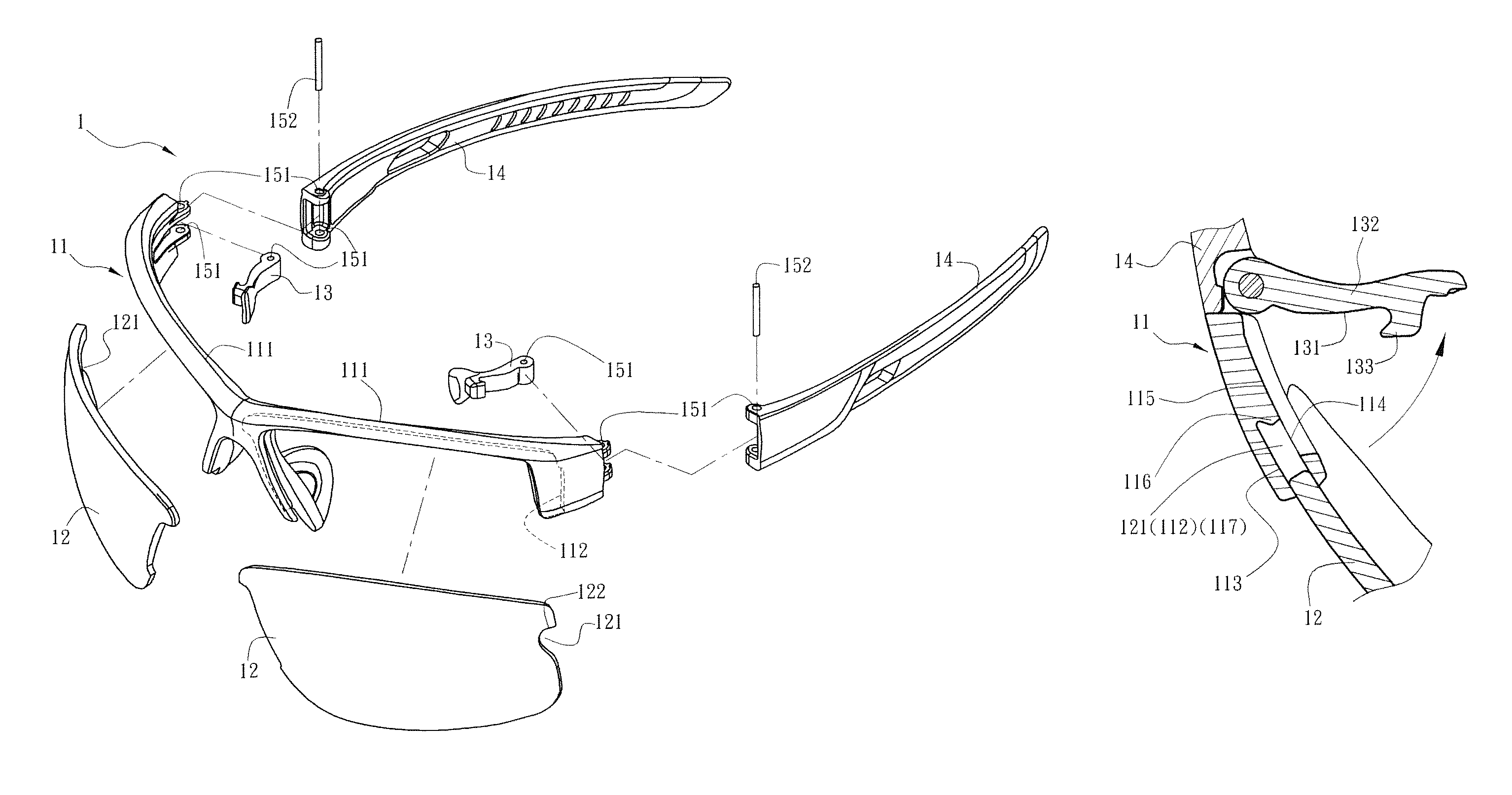
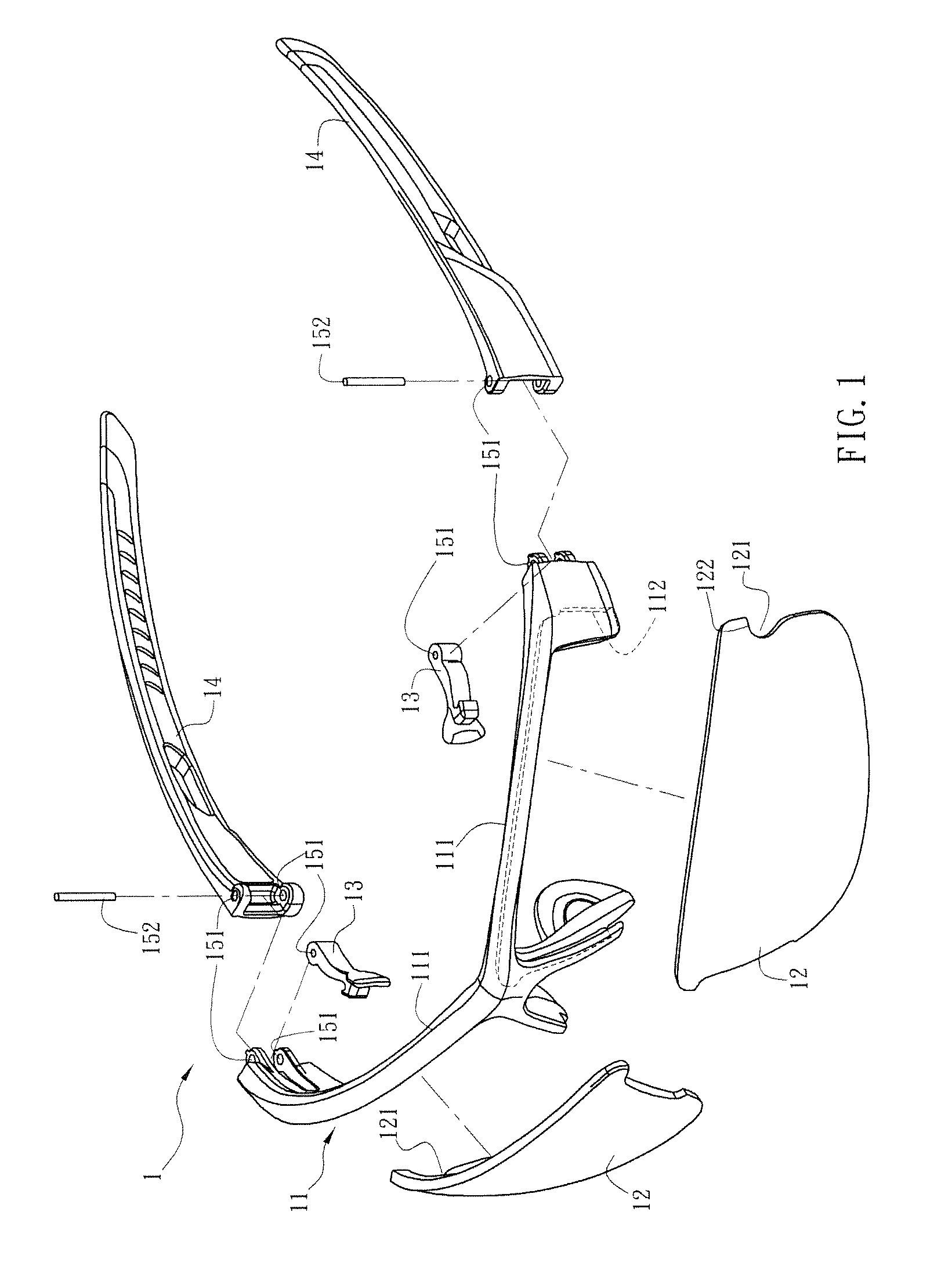
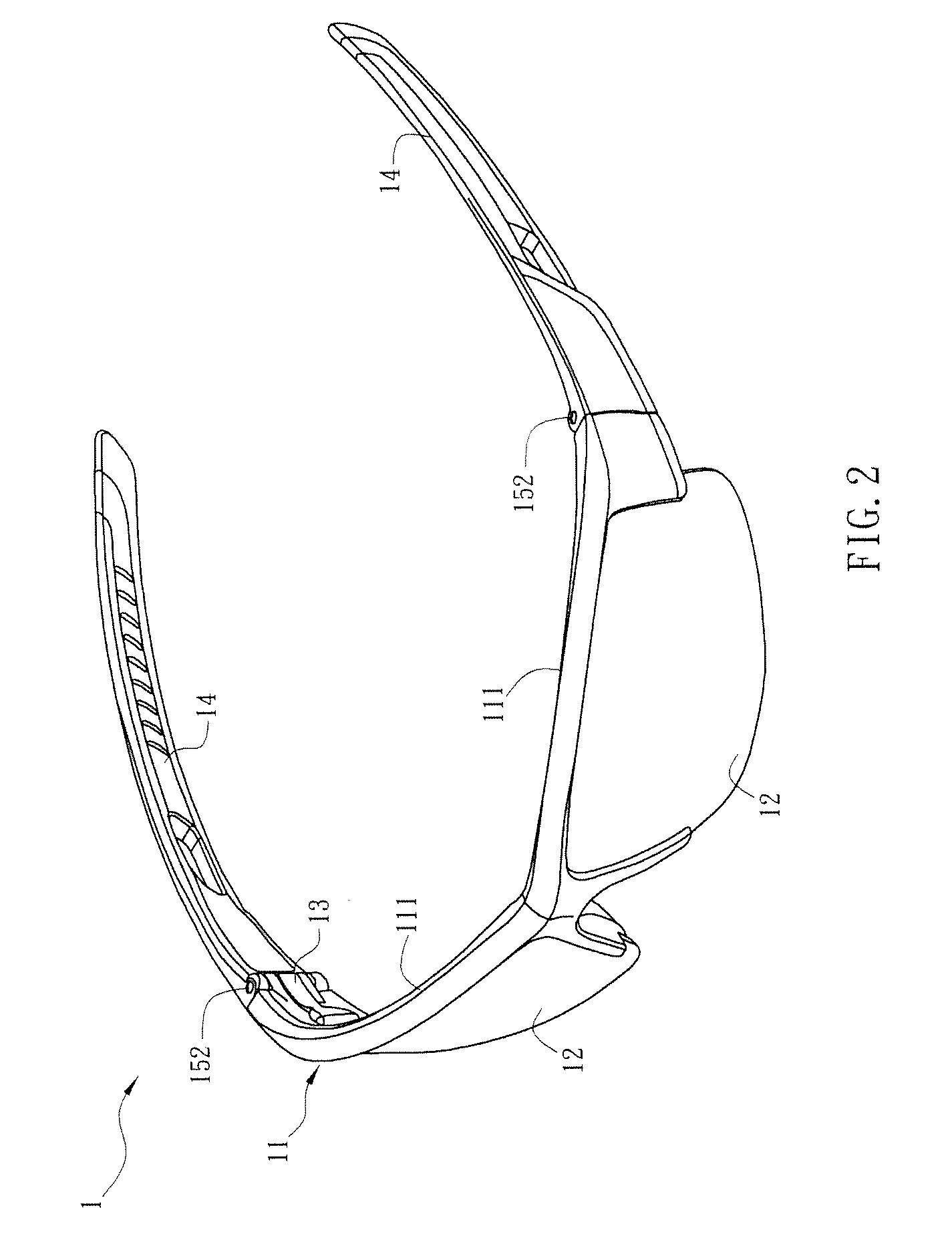
[0022]FIG. 1 is a schematic exploded diagram of a lens device 1 of a preferred embodiment of the invention, and FIG. 2 is a schematic diagram of the lens device 1 in FIG. 1. As shown in FIGS. 1 and 2, the lens device 1 includes a frame 11, at least a lens 12 and two fasteners 13. In the invention, the lens device 1 is not limited in type, which can be sunglasses, working goggles, nearsighted eyeglasses, farsighted spectacles, presbyopia eyeglasses, snow goggles, or the like.

[0023]The frame 11 functions as the main part of the lens device 1. The frame 11 of this embodiment is not limited in shape or curvature, which can be changed according to the practical requirements. The frame 11 is also not limited in material, which can be made by, for example, metal, alloy or plastic material. In this embodiment, the frame 11 has two lens-holding portions 111 for holding two lenses 12. Besides, the lens-holding portion 111 just has an upper portion but without a lower portion. That means the l...


PUM


Abstract

A lens device includes a frame, at least one lens and two fasteners. The frame has at least a lens recess. The lens is embedded in the lens recess, and has an indentation located at an edge of the lens. The fasteners are disposed pivotally to the opposite sides of the frame, respectively, and each have an inner surface, a supporting surface and a hook portion. The inner surface adjoins the supporting surface. The hook portion protrudes from the inner surface. When the fastener rotates so that the hook portion enters into the indentation of the lens, the supporting surface of the fastener is disposed against a side of the indentation.

Description

BACKGROUND OF THE INVENTION[0001]1. Field of the Invention[0002]The invention relates to a lens device.[0003]2. Description of the Prior Art[0004]In general, a pair of eyeglasses mainly includes a frame and two temples respectively pivoted on two sides of the frame. The frame includes two rims, and the inner edge of each of the rims has a slot to hold the corresponding lens. Accordingly, the sidewalls of the slot can block the lenses to prevent them from leaving the frame. In this case, however, the lens needs to be hard pressed into the slot to be fixed to the frame although the frame is a little flexible. In addition, the user's improper assembling might cause the lens or frame to be broken or easily scratched.SUMMARY OF THE INVENTION[0005]In view of the foregoing subject, an objective is to provide a lens device whose lens is easily fixed, and thereby the usability and lifespan of the product can be increased.[0006]To achieve the above objective, a lens device according to this i...

Claims


Application Information

Patent Timeline
Patent Type & Authority Patents(United States)
IPC IPC(8): G02C1/04G02C5/20
CPCG02C5/20G02C1/04G02C5/10G02C2200/04G02C2200/08
Inventor CHEN, CHIH MING
Owner HWA MEEI OPTICAL
Learn More