Areal monitoring using distributed acoustic sensing

a distributed acoustic sensing and areal monitoring technology, applied in the field of reservoir investigation, can solve the problems of suboptimal or even ineffective configuration of the initial deployment of the geophone or hydrophone, and the large number of geophones or hydrophones is relatively expensive to acquire, deploy and maintain, and achieves the effect of inexpensive acquisition, deployment and maintenan

Active Publication Date: 2015-04-14
SHELL USA INC
View PDF55 Cites 2 Cited by
  • Summary
  • Abstract
  • Description
  • Claims
  • Application Information

AI Technical Summary

Benefits of technology

[0009]The present invention provides an areal seismic monitoring system that is inexpensive to acquire, deploy, and maintain, and can be modified as-needed to optimize data collection with respect to a changing subsurface region of interest.
[0010]Because of the adaptability of the present system, it can be used to efficiently collect information in various ways. By way of example only, the system can be used to collect one or more items of information in one configuration and one or more items of information in a second configuration, and the first and second configurations can be selected such that the second item(s) of information differ from the first item(s) of information in one aspect selected from the group consisting of: resolution, coverage area, location, and time. An item of information can be based on one received signal or on a plurality of received signals. Further, an item of information can comprise one or more pieces of data, so that, for example, an item of information can comprise data relating to the physical status of each of a plurality of sections along the length of the cable at a single point in time.

Problems solved by technology

First, it is relatively expensive to acquire, deploy and maintain the large numbers of geophones or hydrophones that are needed in order to monitor a large area for the time periods that are typically involved, which may be on the order of years.
Second, because of the transient nature of certain subsurface features, such as fluid flows, the configuration in which the sensors were originally deployed may be suboptimal or even ineffective over time.

Method used


Image

  • Areal monitoring using distributed acoustic sensing
  • Areal monitoring using distributed acoustic sensing
  • Areal monitoring using distributed acoustic sensing

Examples


Embodiment Construction

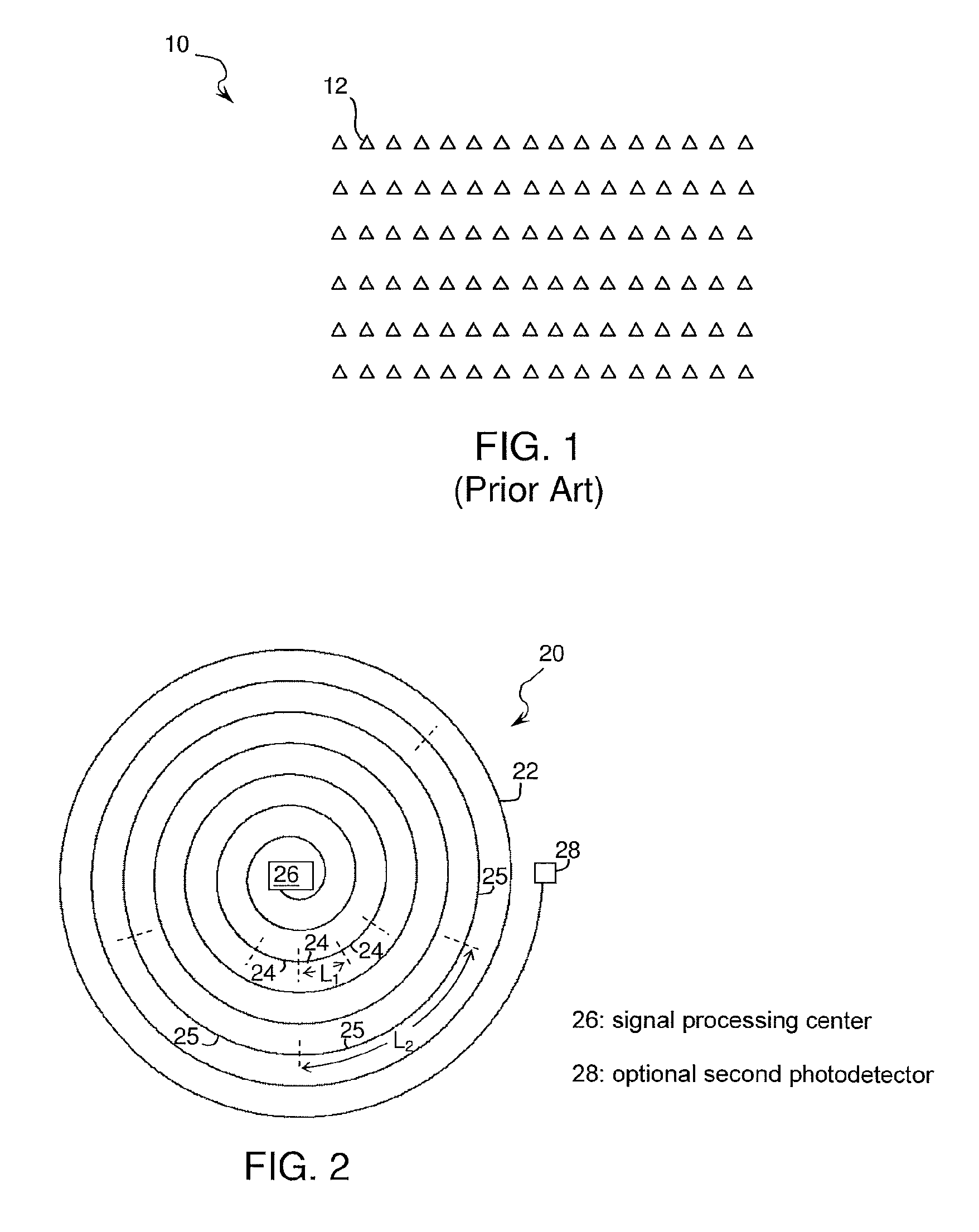
[0025]Referring initially to FIG. 1, an array 10 of conventional acoustic sensors 12 may be deployed as shown. The number of sensors available to cover the desired area is typically limited by cost; once the number of available sensors is established, the sensors are deployed. Sensors may also be deployed in vertical or horizontal boreholes at intermediate depths between the surface and the formations of interest. For on-shore applications, the sensors may be deployed manually, such as by using a GPS system to place each sensor in a desired location, or they may be installed at the bottom of purposely drilled shallow boreholes. For offshore applications, the sensors, referred to as Ocean Bottom Seismometers (OBS) may be deployed by remotely operated vehicle (ROV) and placed on the seabed at desired locations, or they may be deployed in cabled configurations with fixed inter-sensor spacings via Ocean Bottom Cables (OBC) laid on the seabed.

[0026]Regardless of the mode or manner of dep...


PUM


Abstract

A method for obtaining seismic information about a subsurface formation using at least one fiber optic cable having its proximal end coupled to a light source and a photodetector comprises: transmitting into the cable at least one light pulse; receiving at the photodetector a first and second light signals indicative of the physical status of at least one first cable section and at least one second cable section, respectively, wherein the first and second sections are selected so as to provide first and second information items, respectively; optionally, further processing at least one of the first and second information items so as to produce derivative information; and outputting at least one of the first, second, and derivative information items to a display; wherein the second item differs from the first item in at least one aspect selected from the group consisting of: resolution, area, and location.

Description

RELATED CASES[0001]This case is a national stage entry of PCT / US2009 / 060767 filed 15 Oct. 2009, which claims priority from U.S. Provisional Application 61 / 150,842, filed 9 Feb. 2009, both of which are incorporated by reference.FIELD OF THE INVENTION[0002]The invention relates to a method of investigating a reservoir region in a subsurface formation using seismic data. More particularly, the present invention relates to the use of fiber optic cables to provide a system of distributed acoustic sensors that can be actively configured so as to optimize information gained by the investigation.BACKGROUND OF THE INVENTION[0003]Seismic surveys are useful for studying subsurface formations in many contexts, including the monitoring of subsurface hydrocarbon reservoirs and the tracking of fluids, e.g. oil, gas, or water, as they flow through the subsurface strata. One type of areal monitoring that is gaining in importance is the ability to track CO2 that has been injected as part of carbon ca...

Claims


Application Information

Patent Timeline
Patent Type & Authority Patents(United States)
IPC IPC(8): G01V8/16
CPCG01V8/16E21B47/113G01H9/004G01V1/003G01V1/168
Inventor LOPEZ, JORGE LOUISWILLS, PETER BERKELEYMESTAYER, JEFFERY JOSEPH
Owner SHELL USA INC
Why Eureka
Try Eureka