
Internal optical mixer pulsed at larmor frequency

a larmor frequency, optical mixer technology, applied in the direction of wave amplifying devices, laser details, electrical equipment, etc., can solve the problems of limited wavelength range, low beam efficiency, and design efficiency of low and moderate power beams, and achieve high beam quality, efficient amplify pulsed light, and high power

Inactive Publication Date: 2015-04-07
FASORTRONICS
View PDF9 Cites 5 Cited by
  • Summary
  • Abstract
  • Description
  • Claims
  • Application Information

AI Technical Summary

Benefits of technology

This approach enables the generation of pulsed coherent light at previously unavailable wavelengths with high power and beam quality, efficiently amplifying light in the eye-safe range while optimizing wavelength, spectral distribution, and pulse format for applications like sodium excitation, breaking the link between efficiency and depletion.

Problems solved by technology

There is a limited set of wavelengths at which coherent light can be efficiently, reliably, and economically generated using direct laser action.
Such designs tend to be inefficient for beams of low and moderate powers, with only a small fraction of the light converted to the new optical frequency.
For the level of power typically available from practical lasers, Dixon's design will still have low efficiency, especially when robust nonlinear materials such as LBO are used.
When conversion efficiency gets higher, it becomes difficult to generate a beam which has good beam quality.
But if you increase total beam power to improve efficiency off-center, the center back-converts, actually dropping in efficiency, and you get a beam with a dip in the center.
Also, it requires precise matching of the light into the external resonator, creating difficult tolerances on both alignment and cavity length.
Though the Denman design has been successfully used to excite mesospheric sodium atoms, as needed to produce artificial guide stars for astronomy, the lack of modulation reduces the efficiency of sodium excitation, and the challenging tolerances make the design expensive to produce.

Method used


Image

  • Internal optical mixer pulsed at larmor frequency
  • Internal optical mixer pulsed at larmor frequency
  • Internal optical mixer pulsed at larmor frequency

Examples


Embodiment Construction

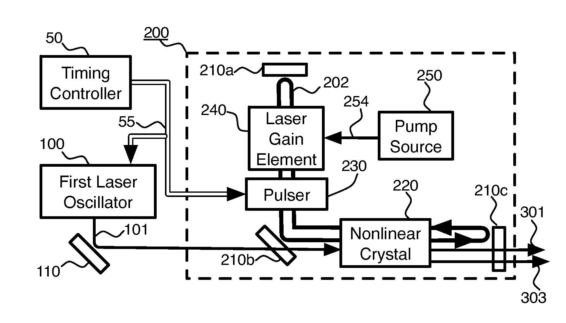
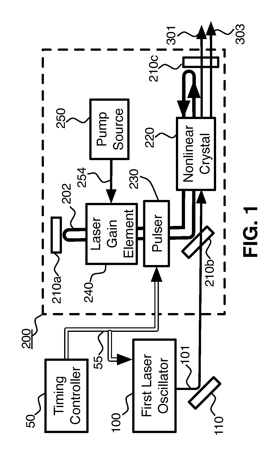
[0059]One embodiment of the generator of coherent light is shown schematically in FIG. 1.

[0060]A laser oscillator 100 produces a beam of coherent light 101 at a wavelength λ1. A pulsed laser 200 comprises resonator mirrors 210a-c, nonlinear crystal 220, pulser 230, and laser gain element 240. Laser gain element 240 is energized, or “pumped,” by energy 254 from pump source 250. The beam of coherent light 101 is directed by turning mirror 110 through resonator mirror 210b, which is transmissive for wavelength λ1, into the nonlinear crystal 220. Turning mirror 110 is one possible means for directing a beam as desired, but many others, including lenses, optical fibers, and prisms, are possible. The nonlinear crystal 220 is inside the resonator of the pulsed laser 200. This resonator is defined by resonator mirrors 210a-c which are arranged so that there is a path for light such that resonant, internally circulating beam 202 will reflect off of each mirror 210a-c and retrace the same pat...


PUM


Abstract

Pulsed, coherent light is generated by optical mixing which takes place inside the resonator of a pulsed laser oscillator. One of the beams to be mixed is generated by the pulsed laser, and the other by a distinct, external laser oscillator. If the light from the external oscillator is modulated, that modulation will be transferred onto the light generated by the optical mixing. Using sum frequency generation, light for sodium excitation, such as for a guide star, can be generated with the optimal modulation of spectral and temporal properties. If the pulse repetition frequency is chosen to be at or near the magnetic (Larmor) resonance of the sodium, then the amount of scattered light due to sodium excitation is enhanced, and the magnetic field at the location of the sodium atoms can be measured.

Description

STATEMENT OF GOVERNMENT INTEREST[0001]This invention was made with U.S. Government support under contract No. N00014-11-0314, awarded by the Office of Naval Research. The U.S. Government has certain rights in this invention.TECHNICAL FIELD OF THE INVENTION[0002]This application relates to the generation and amplification of coherent optical radiation.BACKGROUND OF THE INVENTION[0003]In this document, I will use the word “light” interchangeably with “optical radiation,” understanding that a range of invisible wavelengths which propagate similarly to light are included when either term is used.[0004]The most common techniques for generating coherent light involve laser action. Laser action occurs when atoms or molecules in their excited state generate and amplify light at a specific wavelength determined by the energy difference between the excited state and the unexcited state of the atom or molecule. There is a limited set of wavelengths at which coherent light can be efficiently, r...

Claims


Application Information

Patent Timeline
Patent Type & Authority Patents(United States)
IPC IPC(8): H01S3/10H01S3/11
CPCH01S3/11H01S3/0815H01S3/083H01S3/10092H01S3/1083H01S3/115H01S3/1611H01S3/2316H01S3/2391H01S3/0085H01S3/1643H01S3/0092
Inventor KANE, THOMAS JAMES
Owner FASORTRONICS
Learn More