Eureka AIR delivers breakthrough ideas for toughest innovation challenges, trusted by R&D personnel around the world.

Braking system, rollator and transport chair with the same

a technology of braking system and rollator, which is applied in the direction of braking system, wheelchair/patient conveyance, friction lining, etc., can solve the problems of unactuated braking system, danger to the user sitting on the conventional rollator, and movable conventional rollator

Active Publication Date: 2015-04-07
FLYING EAGLE TECH
View PDF40 Cites 53 Cited by
  • Summary
  • Abstract
  • Description
  • Claims
  • Application Information

AI Technical Summary

Benefits of technology

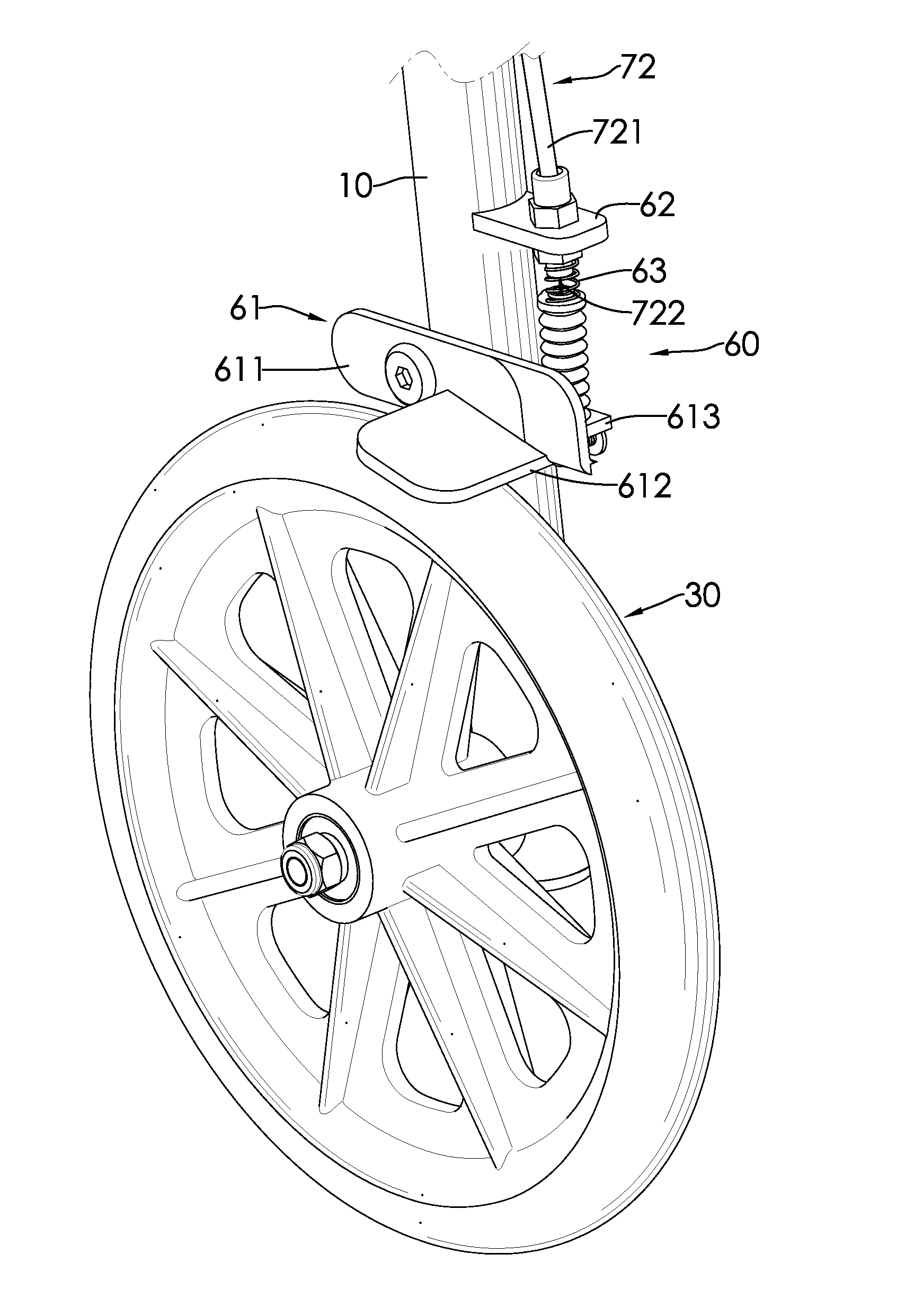
[0014]When the operating system is unactuated, the braking system is actuated and the braking part tightly abuts the surface of the corresponding wheel to avoid a rotation of the wheel. When the user wants to walk and move the present invention, the user has to press the operating system to make the braking part depart from the surface of the corresponding wheel to release the brake. When the user wants to rest on the seat cushion, the user can keep the braking system actuated without pressing the operating system, and the rollator would not be moveable and slidable when sat on, thereby avoiding danger. In addition, if the user needs to grasp something else by two hands when walking on a slope, the user can just release the present invention without worrying that sliding of the present invention would cause danger.

Problems solved by technology

First, the braking system relies on manual operation. If the user forgets to press the operating part when sitting on the seat cushion, the conventional rollator is movable and is dangerous for the user sitting on the conventional rollator.
Second, the user has to continuously press the operating part to keep the braking system actuated. If the user unexpectedly needs both hands for grasping something else when walking on a slope, the braking system turns unactuated and the conventional rollator may slide down the slope, causing danger to the user.

Method used


Image

  • Braking system, rollator and transport chair with the same
  • Braking system, rollator and transport chair with the same
  • Braking system, rollator and transport chair with the same

Examples


Embodiment Construction

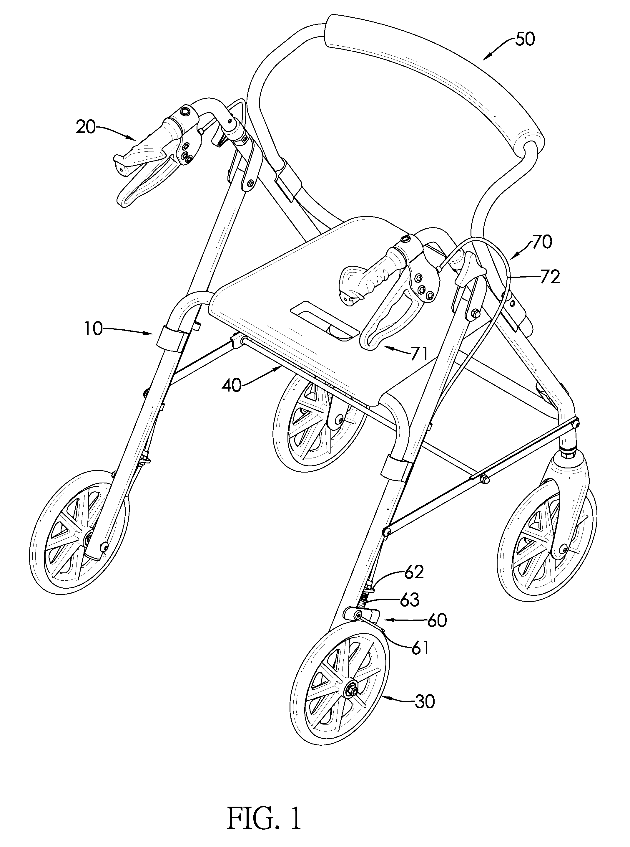
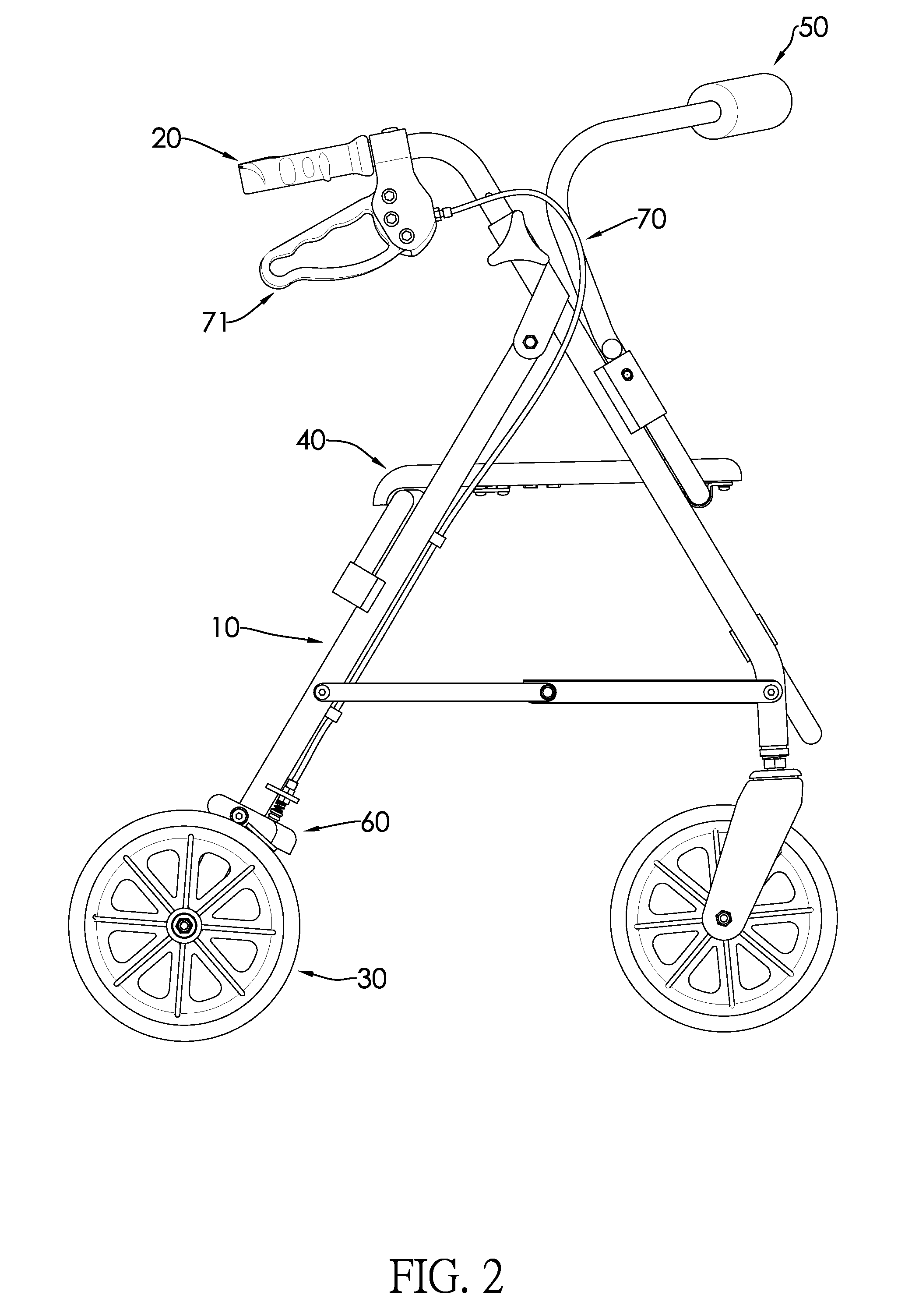
[0024]With reference to FIGS. 1 and 2, a rollator in accordance with the present invention comprises a stand 10, two handles 20, at least three wheels 30, a seat cushion 40, at least one braking system 60 and at least one operating system 70. In a preferred embodiment, the rollator further comprises a seatback 50.

[0025]With reference to FIGS. 2 and 3, in a preferred embodiment, the stand 10 is foldable and composed of at least two stand bodies pivotally connected to each other. When the rollator is not in use, the rollator can be folded to reduce a storage space.

[0026]With reference to FIGS. 1 and 2, the handles 20 are respectively mounted on two top ends on two sides of the stand 10. In a preferred embodiment, the handles 20 both extend to a rear of the stand 10.

[0027]In a preferred embodiment, the rollator comprises four wheels 30 arranged in a rectangle and mounted on a bottom of the stand 10, wherein two of the front wheels 30 are mounted on a pivot base. The pivot base is mount...


PUM


Abstract

A braking system is mounted on a rollator or a transport chair and includes a braking part and an operating system. The braking part is mounted adjacent to a wheel of a rollator or a transport chair. When the operating system is unactuated, the braking part abuts a corresponding wheel to avoid a rotation of the corresponding wheel. When a user wants to walk and move the rollator or the transport chair, the user can press the operating system such that the braking part departs from the wheels and releases a brake. When the user wants to sit on the seat cushion and rest, the user can keep the braking system actuated without pressing the operating system, and accordingly the rollator or the transport chair would not be slidable when sat on, thereby avoiding danger. In addition, when the user walks on a slope, the user can release their hands from the rollator or the transport chair without making the rollator or the transport chair slide down the slope.

Description

BACKGROUND OF THE INVENTION[0001]1. Field of the Invention[0002]The present invention relates to a braking system, a rollator and a transport chair with the same, and more particularly to a rollator and a transport chair helping an older or a patient to walk.[0003]2. Description of Related Art[0004]A rollator is an auxiliary appliance for users in need of mobility aids to walk and to keep balance.[0005]A conventional rollator has a stand, two handles, four wheels, a seat cushion, a seatback, a braking system and an operating system. The handles are respectively mounted on two sides of the stand and face the same direction. The wheels are mounted rotatably on a bottom of the stand and are arranged in a rectangle. The seat cushion is mounted on the stand and is mounted between the handles and the wheels. The seatback is also mounted on the stand above a side of the seat cushion. The braking system is mounted on the stand and adjacent to one of the wheels. The operating system is mount...

Claims


Application Information

Patent Timeline
Patent Type & Authority Patents(United States)
IPC IPC(8): B62M1/00F16D59/02A61G5/10A61H3/04B60T1/04B60T7/08B60T7/10B60T11/04F16D49/00F16D69/00F16D125/60
CPCF16D59/02A61G5/101A61H3/04B60T1/04B60T7/08B60T7/102B60T7/104B60T11/046F16D49/00F16D2069/004F16D2125/60A61G5/1018A61G5/1037A61H2003/046A61H2201/0161A61H2201/1633
Inventor CHANG, LING-SENG
Owner FLYING EAGLE TECH
Why Eureka
Eureka Blog
Learn More