Electronic timepiece with internal antenna

an electronic timepiece and antenna technology, applied in the direction of antennas, antenna details, instruments, etc., can solve the problems of affecting the view of the time display and increasing the size of the electronic timepiece accordingly, and achieve the effect of suppressing the size increase, easy reading, and good reception performan

Active Publication Date: 2015-03-31
SEIKO EPSON CORP
View PDF11 Cites 5 Cited by
  • Summary
  • Abstract
  • Description
  • Claims
  • Application Information

AI Technical Summary

Benefits of technology

[0008]The present invention is directed to the foregoing problem, and achieves a time display that can be easily read and an antenna with good reception performance while suppressing increasing the size of an electronic timepiece that has an internal antenna.
[0010]Because the base of the antenna has a sloped face and this face decreases in height to the time display unit with proximity to the inside, the time display unit (such a timepiece dial) can be seen from a wide angle of view. Furthermore, because a conductive antenna element through which the antenna is fed is disposed to this slope, the antenna element can be disposed to a position where radio waves from the outside cannot be easily blocked by the case, at least part of which is made from a conductive material. The acceptance angle of the antenna element is therefore wide, and good reception performance can be assured in the antenna.
[0011]Because using such a slope makes the time display unit easy to see and increases the acceptance angle of the antenna element, there is no need to create a wide area around the outside of the time display unit, and increasing the size of the electronic timepiece can be suppressed.
[0018]In the electronic timepiece according to this aspect of the invention, the ground potential is stabilized and good reception performance can therefore be assured in the antenna as a result of the case body and the back cover, which have a large volume and area, functioning as a ground plane.
[0020]Because the bezel that holds the crystal attached to the case is made of a non-conductive material, the bezel does not interfere with signal reception by the antenna. The bezel is fit to the inside of the body, and the bezel increases the distance between the conductive body and the antenna, and more particularly the conductive part of the antenna. The acceptance angle through which the antenna can receive signals is therefore increased, and good reception performance can be assured.
[0022]The body of the casein this aspect of the invention is made of a conductive material, but by disposing the body closer in height to the time display unit than the antenna element of the antenna, the body has substantially no effect on the directions from which radio waves can reach the antenna element. The acceptance angle through which the antenna element can receive signals is therefore increased, and good reception performance can be assured.

Problems solved by technology

If the ring-shaped antenna disposed around the time display is located too close to the time display, viewing the time display may be obstructed.
However, disposing the antenna to a position far from the time display requires a large area outside of the time display, and the size of the electronic timepiece increases accordingly.

Method used


Image

  • Electronic timepiece with internal antenna
  • Electronic timepiece with internal antenna
  • Electronic timepiece with internal antenna

Examples


Embodiment Construction

[0042]Preferred embodiments of the present invention are described below with reference to the accompanying figures. Note that the size and scale of parts shown in the figures differ from the actual size and scale for convenience. Furthermore, the following examples are specific preferred embodiments of the invention and describe technically desirable limitations, and the scope of the invention is not limited thereby unless such limitation is specifically stated below.

A. Mechanical Configuration of an Electronic Timepiece with Internal Antenna

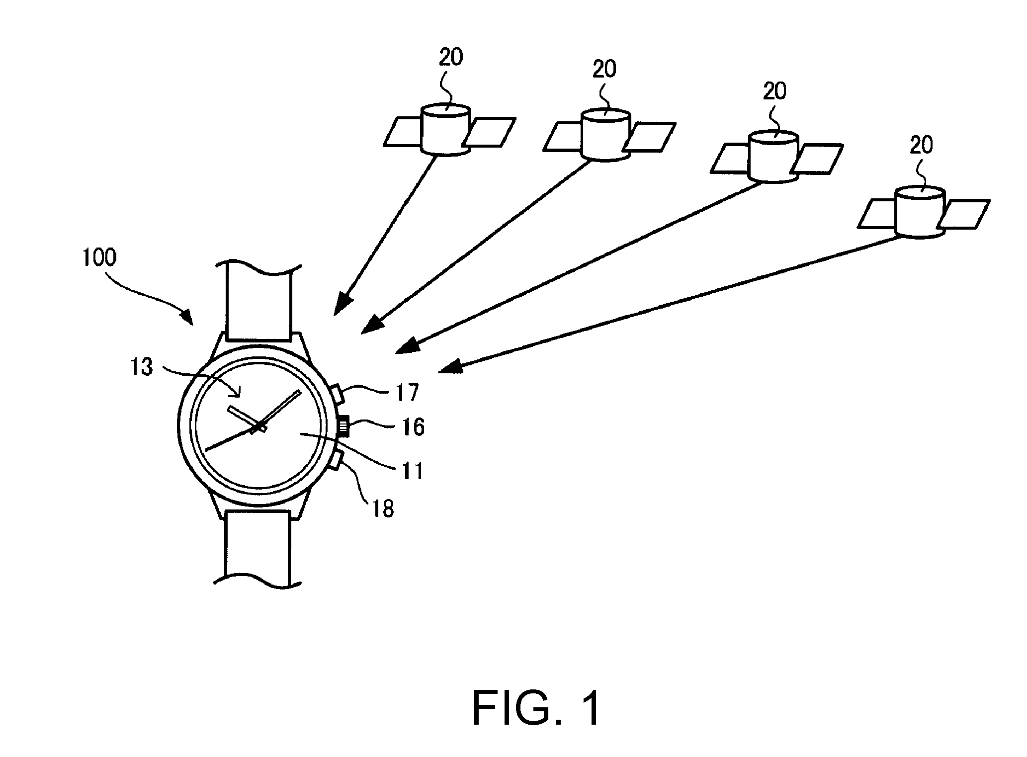
[0043]FIG. 1 shows the basic concept of a GPS system that includes an electronic timepiece 100 with an internal antenna according to a preferred embodiment of the invention.

[0044]The electronic timepiece 100 is a wristwatch that receives signals (radio signals) from at least one of plural GPS satellites 20 and adjusts the time based thereon, and displays the time on the surface (side) (referred to below as the “face”) on the opposite side as th...


PUM


Abstract

An electronic timepiece has a case of which at least part is made from a conductive material; an annular antenna housed in the case; and a dial disposed inside the antenna. The antenna has an annular dielectric base. The base has a sloped surface that slopes toward the dial and decreases in height to the dial with proximity to the inside. The antenna element is made from a conductive material and is fed by the feed part of the antenna, and is disposed to the sloped surface of the base.

Description

BACKGROUND[0001]1. Technical Field[0002]The present invention relates to an electronic timepiece with an internal antenna.[0003]2. Related Art[0004]Electronic timepieces that receive signals from positioning information satellites such as GPS (Global Positioning System) satellites to display accurate time are known from the literature. Such electronic timepieces commonly have a ring-shaped antenna for receiving radio signals from the positioning information satellites. See, for example, Japanese Unexamined Patent Appl. Pub. JP-A-2011-21929, and Japan Patent No. 4551678.[0005]The ring-shaped antenna is disposed around the time display part (such as the dial) of the electronic timepiece. The antenna includes an annular base made of a dielectric material (an electrical insulator), and an annular part made of a conductive material formed on the base.[0006]If the ring-shaped antenna disposed around the time display is located too close to the time display, viewing the time display may be...

Claims


Application Information

Patent Timeline
Patent Type & Authority Patents(United States)
IPC IPC(8): G04R60/12G04R20/04G04R60/10
CPCG04R60/10G04R60/12G04R20/04
Inventor FUJISAWA, TERUHIKO
Owner SEIKO EPSON CORP
Why Eureka
Try Eureka