
Video output apparatus and video output method

a video output and video technology, applied in the field of video output apparatus and video output method, can solve the problems of wasting unnecessary time and effort, affecting the user's comprehension of what has been displayed, and the display area of the window currently used may be small, so as to save power of the display device and quickly determine the window that a user can us

Inactive Publication Date: 2015-03-24
CANON KK
View PDF19 Cites 4 Cited by
  • Summary
  • Abstract
  • Description
  • Claims
  • Application Information

AI Technical Summary

Benefits of technology

[0016]The present invention is directed to a method for adequately saving power of a display device and quickly determining a window that a user desires to use.

Problems solved by technology

Thus, it is difficult for the user to comprehend what has been displayed and which display the user desires to use has been displayed before the power saving is performed at sight.
This takes unnecessary time and effort.
Further, even if the multi display system is used, a display area of the window currently used may be small depending on arrangement of the window.
In this case, although the windows can be displayed on one screen, since they are displayed using two screens, unnecessary power is used.
Generally, since the position and size of a window the user uses depend on an operation by the user, it is assumed that the unnecessary power is often used as described above.
Thus, if there is no input from such a device for a certain period of time, all the displays will be in a non-display state, and the user will not be able to see an object on the display that the user desires to see.
Further, when the total area of the windows displayed on the screen of the multi display unit is small, all the display units will be in a non-display state due to power saving reasons.
Even if the user desires to arrange the windows in a smaller number of display devices, since the power of each display cannot be individually managed, the power of each display device cannot be turned off.
Accordingly, power saving cannot be performed.
Thus, it is difficult for the user to know the window that has been displayed before the power saving.
Further, when a window that the user newly opens is arranged on a screen of a display in the non-display state, the user cannot quickly determine a display on which the new window is displayed.
Further, even if the total area of the windows displayed on the screen of the multi display unit is small, the user needs to direct his line of sight to all the display devices to turn them on.
Thus, power is not saved as intended.
Similarly, the technique discussed in the Japanese Patent Application Laid-Open No. 2000-163035 is not usable in determining which window has been displayed before the power saving is performed.
Thus, power is not saved as intended.

Method used


Image

  • Video output apparatus and video output method
  • Video output apparatus and video output method
  • Video output apparatus and video output method

Examples


Embodiment Construction

[0035]Various exemplary embodiments, features, and aspects of the invention will be described in detail below with reference to the drawings.

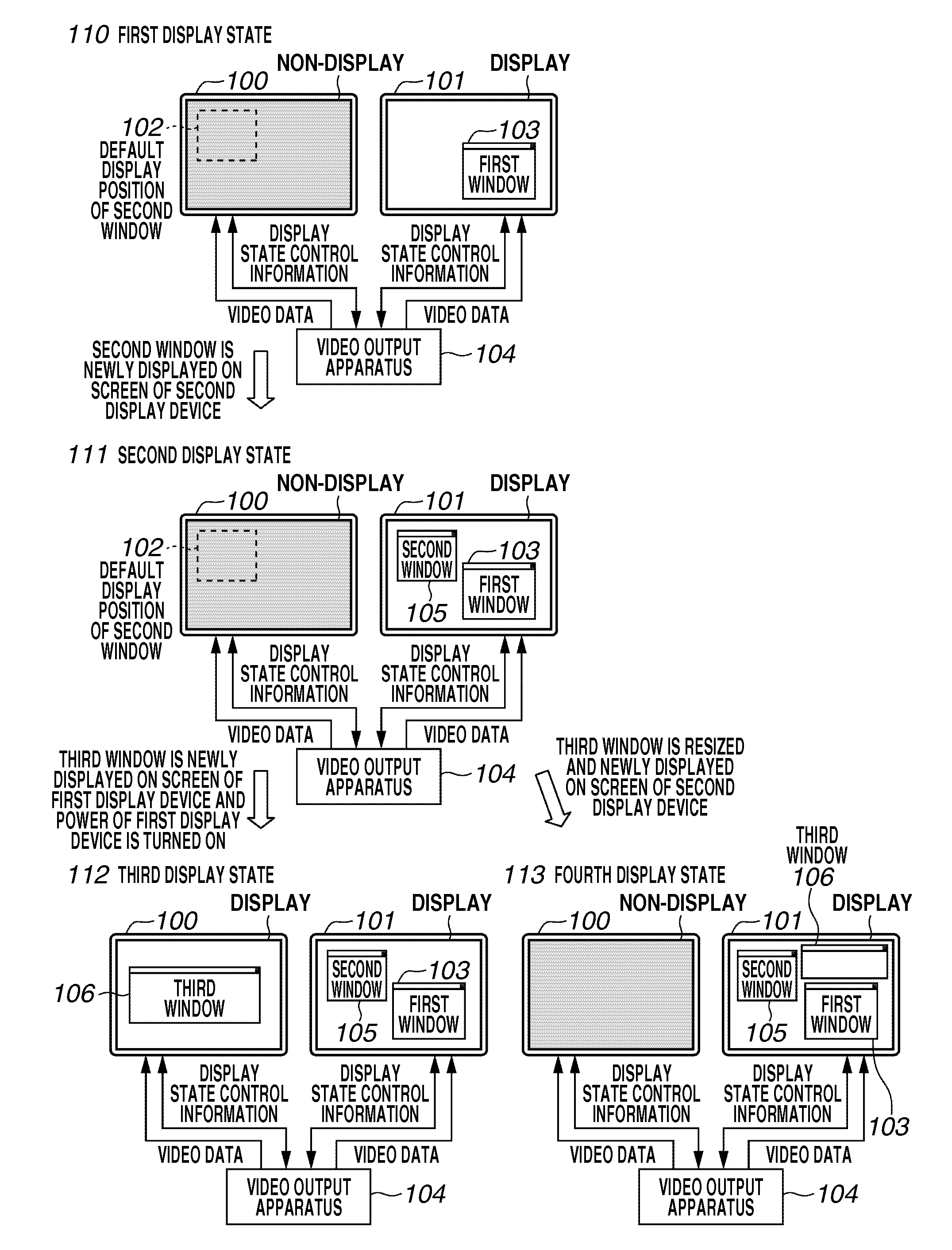
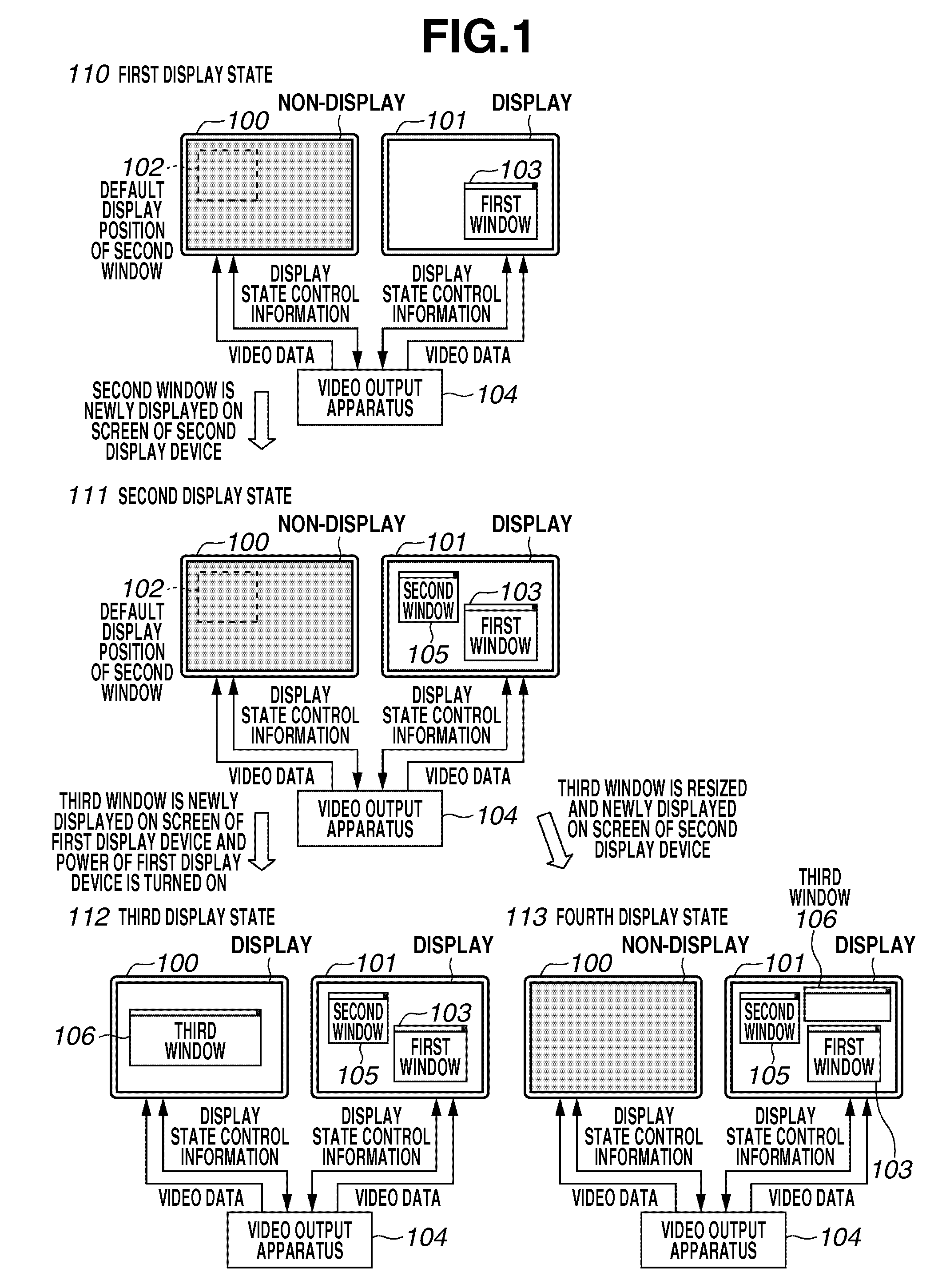
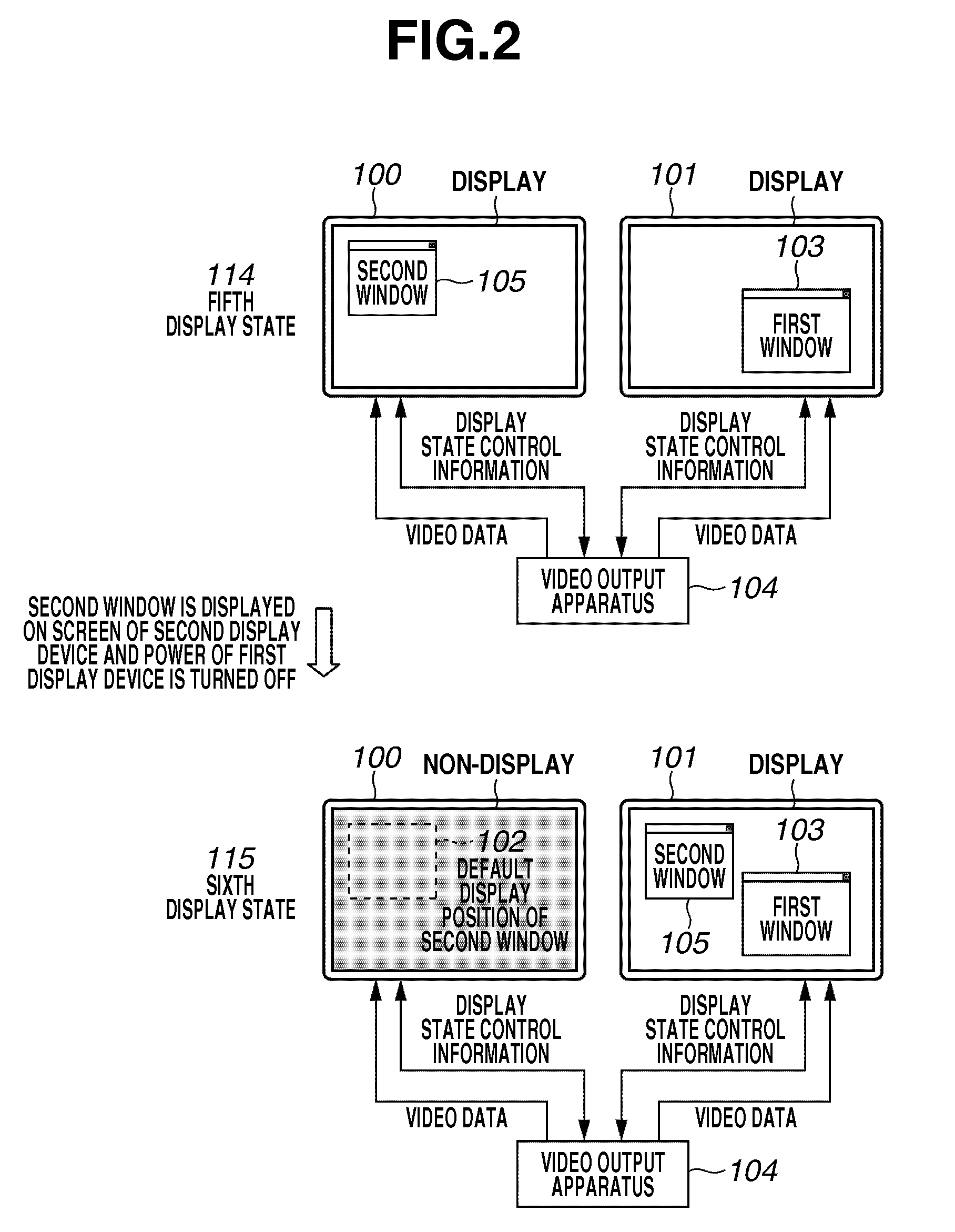
[0036]According to an exemplary embodiment, a configuration of a video output apparatus and processing flow will be described with reference to FIG. 5. Then, detailed processing of each unit will be described with reference to FIGS. 6 to 15. After then, each of functions realized by the present exemplary embodiment will be described with reference to FIGS. 1 to 4.

[0037]FIG. 5 is a block diagram illustrating an example of a configuration of a main portion of a video output apparatus 500 according to the present exemplary embodiment. The video output apparatus 500 according to the present exemplary embodiment can save power of a first display device 503 and a second display device 505 by controlling generation of video data and display states of the first display device 503 and the second display device 505. The flow of the processing will be des...


PUM


Abstract

A video output apparatus of the present invention includes an acquisition unit configured to acquire information about display states of a plurality of display devices, a video output unit configured to output video data to the display devices, and a control unit configured to, when a display device to which the video data is output by the video output unit is in a display state of OFF, control the video output unit to output the video data to a display device whose display state is ON based on the information about the display state acquired by the acquisition unit.

Description

BACKGROUND OF THE INVENTION[0001]1. Field of the Invention[0002]The present invention relates to a video output apparatus, a video output method, a program, and a storage medium. More particularly, the present invention relates to a technique useful for saving power of a multi display system.[0003]2. Description of the Related Art[0004]Conventionally, there is a technique used in reducing power consumption of information processing terminals. According to this technique, power of a device connected to he information processing terminal is turned off according to its usage state, so that the power consumption can be reduced. In the information processing terminal, there is provided, for example, a timer for measuring a time period that the device connected to the information processing terminal is used. When the device is not used, the timer counts up. If the device is unused for a certain period of time and a count value of the timer reaches a certain value, the power of the corresp...

Claims


Application Information

Patent Timeline
Patent Type & Authority Patents(United States)
IPC IPC(8): G09G5/00G06F3/048G06F3/0484G06F3/14G09G5/14
CPCG06F3/1431G09G5/14G09G2330/021G09G2330/022G09G2340/12G09G2370/045
Inventor KITASHOU, TETSUROU
Owner CANON KK
Learn More