
Drive control method of reception unit and positioning device

a technology of positioning device and drive control, which is applied in the direction of power management, instruments, high-level techniques, etc., can solve the problems of reducing the accuracy of measured position, prolonging the time required for positioning, and inability to acquire position logs when the gps is used

Inactive Publication Date: 2015-06-25
SEIKO EPSON CORP +1
View PDF3 Cites 3 Cited by
  • Summary
  • Abstract
  • Description
  • Claims
  • Application Information

AI Technical Summary

Benefits of technology

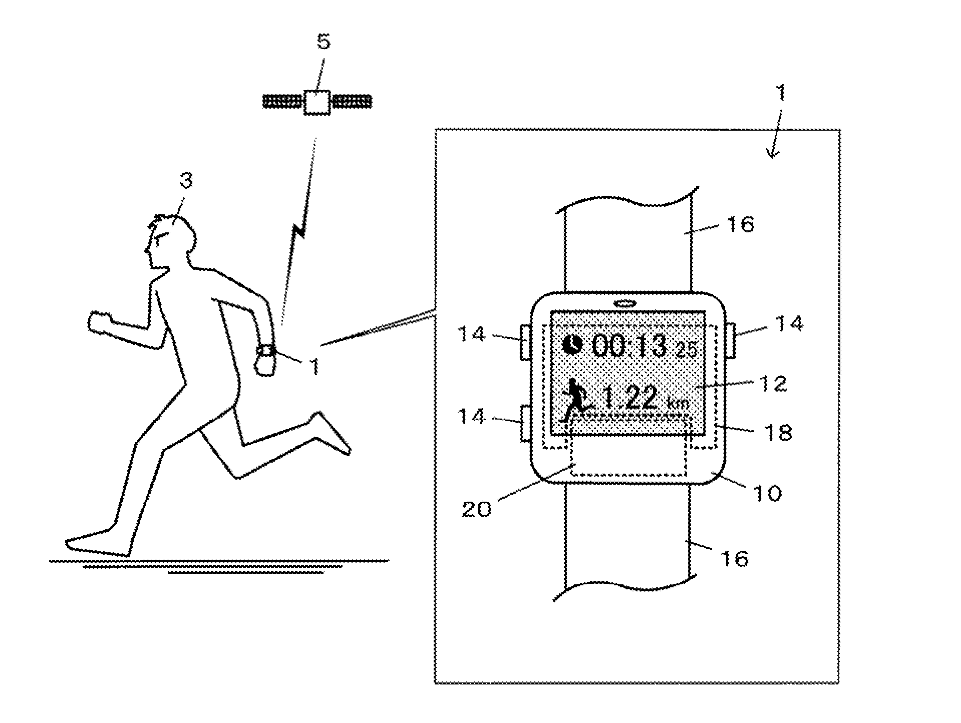
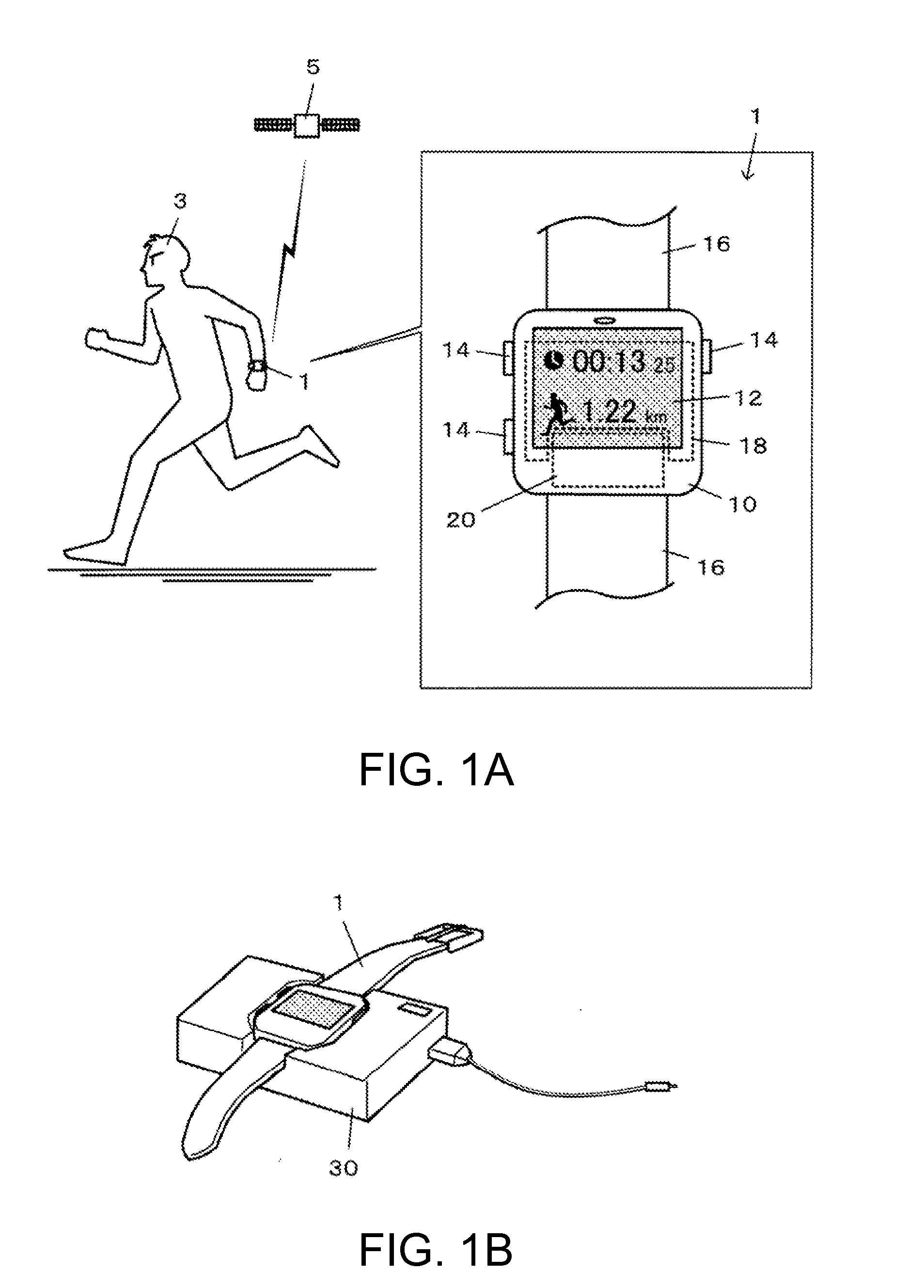
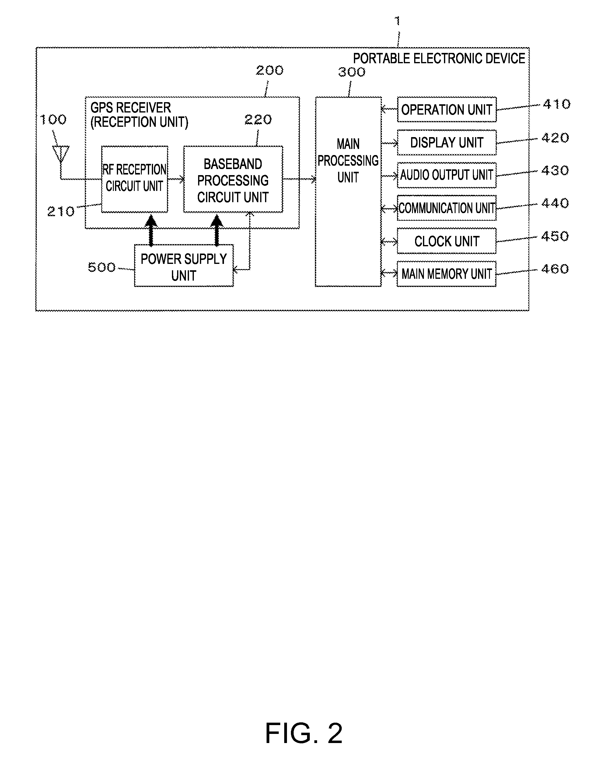
The invention provides a new method for saving power in a positioning device that receives a positioning signal. The method involves setting an intermittent operation range for the reception unit based on the power consumption status of the power supply unit that supplies the reception unit with power. This range is determined by setting the upper limit of the operation ratio of the reception unit based on the remaining power level of the power supply unit. The reception unit then performs intermittent operation within this range. This method can be implemented based on the remaining power level of the power supply unit, the output voltage of the power supply unit, the positioning operation time, or the movement speed of the positioning signal. The intermittent operation range can also be varied based on the data portion of the navigation message carried on the positioning signal. The technical effect of this invention is to reduce power consumption in the positioning device, extending the operation time of the device.

Problems solved by technology

However, in the technology of JP-A-10-332414 described above, a reception interval of the GPS satellite signals may be long, for example, one minute, and thus there is a disadvantage in that position logs cannot be acquired when the GPS satellite signals are not received.
During intermittent positioning in which the reception interval is long, it is difficult to capture continuous GPS satellite signals, which can lead to a decrease in an accuracy of the measured position, and prolonged time required for positioning.

Method used


Image

  • Drive control method of reception unit and positioning device
  • Drive control method of reception unit and positioning device
  • Drive control method of reception unit and positioning device

Examples


modification example

[0078]In addition, the applicable embodiment of the invention is not limited to the embodiment described above, and it is of course that the invention may be appropriately changed without departing from the scope of the invention.

A. Power Consumption Status of Power Supply Unit 500

[0079]For example, the output voltage of the power supply unit 500 and the positioning operation time may be determined as the power consumption status of the power supply unit 500. The output voltage of the power supply unit 500 decreases with a decrease in the remaining amount of power.

[0080]Therefore, for example, the threshold of the output voltage corresponding to the remaining amount of power (for example, 20%) that is considered to be “small” is preset, and if the output voltage of the power supply unit 500 is less than the threshold voltage, the upper limit of the operation range is set to be low.

[0081]Further, the positioning operation time is the accumulated time of the positioning operation (pos...


PUM


Abstract

A portable electronic device includes a reception unit (GPS receiver) that receives a positioning signal, and a power supply unit that supplies the reception unit (GPS receiver) with power. An intermittent operation range including an upper limit of an operation ratio of the reception unit (GPS receiver) is set, based on power consumption status of the power supply unit. The reception unit (GPS receiver) is intermittently operated within the intermittent operation range that is set.

Description

[0001]The entire disclosure of Japanese Patent Application No. 2013-263485, filed Dec. 20, 2013 is hereby expressly incorporated by reference herein.BACKGROUND[0002]1. Technical Field[0003]The present invention relates to a drive control method of a reception unit or the like.[0004]2. Related Art[0005]Portable electronic devices on which positioning devices represented by Global Positioning System (GPS) receivers are mounted have become widespread. The positioning device receives positioning signals which are GPS satellite signals and the like so as to measure and output positions, speeds, and the like, but when the positioning devices are mounted on the portable electronic devices, saving power consumption is required in order to extend measurement time. For example, JP-A-10-332414 discloses a technology of enabling a reduction in power consumption by changing a reception interval of a GPS satellite signal depending on a movement distance.[0006]However, in the technology of JP-A-10...

Claims


Application Information

Patent Timeline
Patent Type & Authority Applications(United States)
IPC IPC(8): H04W52/02H04W4/02
CPCH04W52/0251H04W52/0261H04W4/02G01S19/34Y02D30/70
Inventor YAMAMURA, YOSHIHIROHIRAKAWA, RYOTA
Owner SEIKO EPSON CORP
Learn More