Chain transmission device

a transmission device and chain technology, applied in the direction of driving chains, belts/chains/gearrings, driving chains, etc., can solve the problems of impaired power transmission efficiency, reduce the weight of wrapping parts, reduce the noise and friction of impact, and restrict the side-slip of chains

Inactive Publication Date: 2015-03-24
TSUBAKIMOTO CHAIN CO
View PDF7 Cites 0 Cited by
  • Summary
  • Abstract
  • Description
  • Claims
  • Application Information

AI Technical Summary

Benefits of technology

[0010]The contact guide plates of the contact guide rows restrict sideslip of the chain. However, because some of the guide rows of the chain are non-contact guide rows having only non-contact guide plates, the number of the guide rows that come into contact with side surfaces of the sprockets and the sprocket teeth is reduced. Consequently, noise and friction caused by the contact between guide plates and the sprocket side surfaces are reduced, and power transmission can take place more efficiently. In addition, because the non-contact guide plates are lighter in weight than the contact guide plates, impact noise generated when the contact guide plates come into contact with the sprocket side surfaces is reduced. The weight of the chain is also reduced, and therefore the overall weight of the machinery of which the chain is a part is reduced.
[0011]According to a second aspect of the invention, at least one of the wrapping portions of the chain always includes at least one contact guide row having at least one contact guide plate, and a plurality of non-contact guide rows each having only non-contact guide plates. Here, because at least one of the wrapping portions always includes a contact guide row, it is possible to restrict sideslip of the chain. Because at least one of the wrapping portions always includes a plurality of the non-contact guide rows, the weight of the wrapping portions is reduced, and impact noise and friction loss are reduced.
[0012]According to a third aspect of the invention, in each of the wrapping portions, the number of non-contact guide rows is always greater than the number of contact guide rows. Here, because the wrapping portions always include a larger number of non-contact guide rows than contact guide rows, the weight of the wrapping portions is still further reduced. Thus, it is possible to realize a further decrease in impact noise and friction.
[0017]Here, because at least one of the wrapping portions always includes at least one type 1 contact guide row and at least one type 2 contact guide row, it is possible to restrict sideslip of the chain bidirectionally.
[0019]According to a seventh aspect of the invention, one of the pair of guide plates of at least one of the contact guide rows is a contact guide plate and the other guide plate of the pair is a non-contact guide plate. Here it is possible not only to restrict sideslip of the chain, but also to reduce the weight of the wrapping portions, and to decrease impact noise and friction.
[0020]According to an eighth aspect of the invention, a plurality of the contact guide rows are arranged randomly in the lengthwise direction of the chain. Here, because contact between the guide plates and the sprocket side surfaces does not occur at regular intervals, periodic contact noise is decreased.

Problems solved by technology

In addition, power transmission efficiency is impaired by friction between the guide plates 540 and the sprocket side surfaces 512.

Method used


Image

  • Chain transmission device
  • Chain transmission device
  • Chain transmission device

Examples


second embodiment

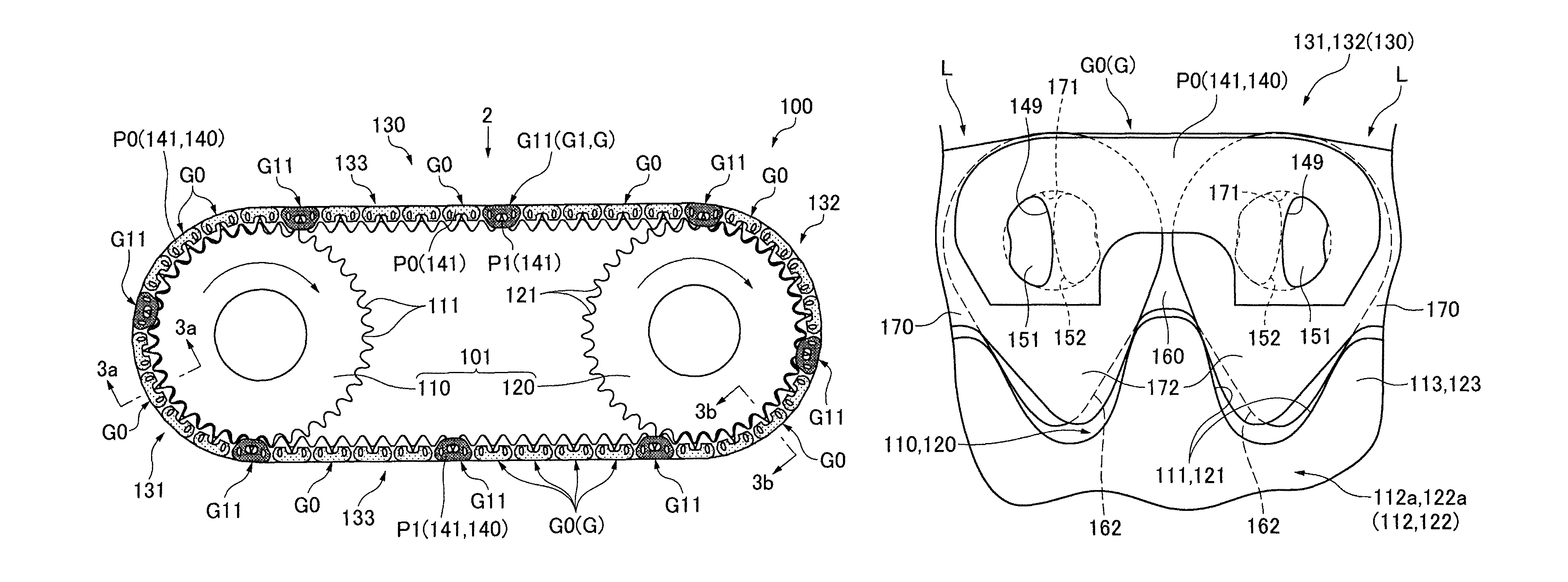
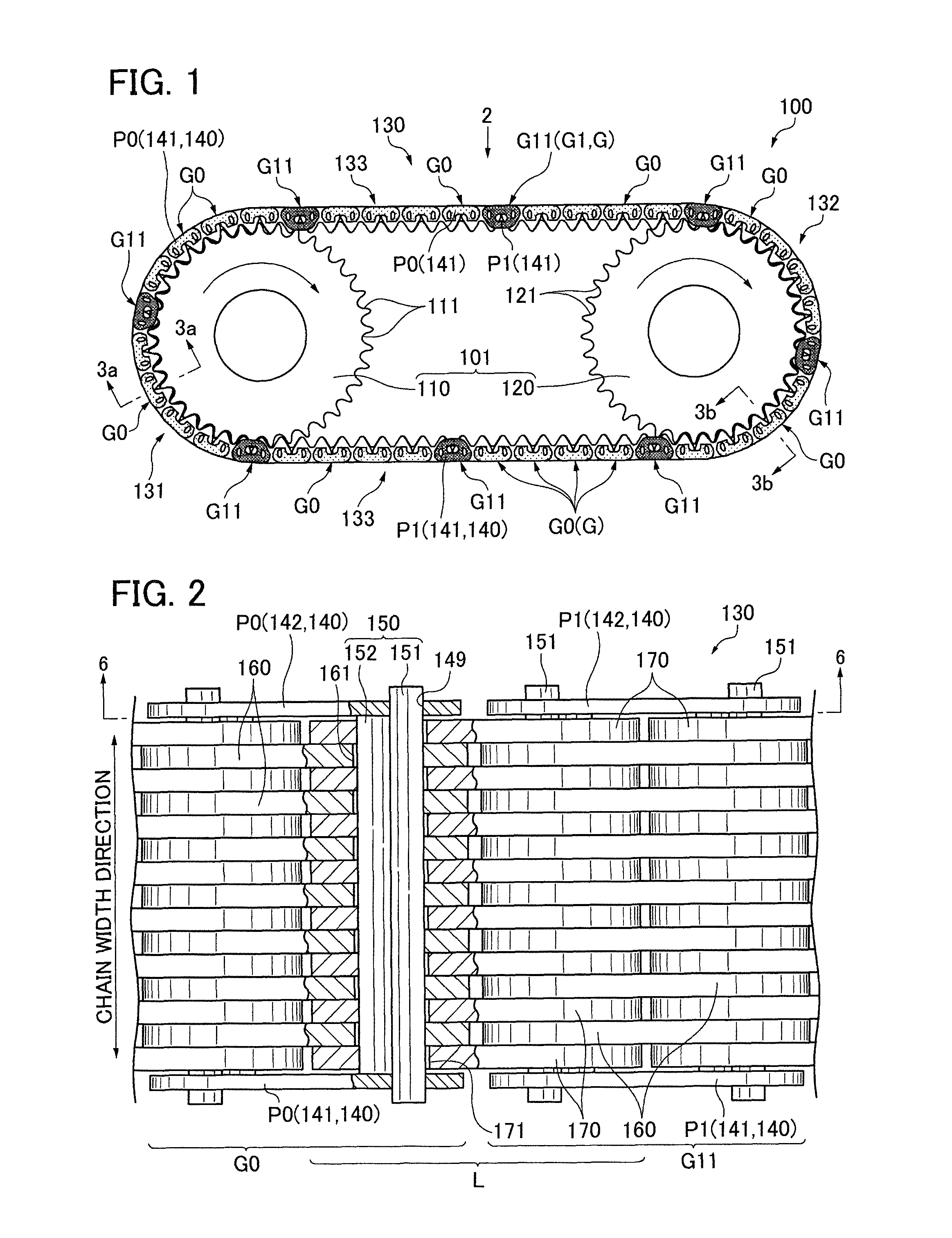
[0059]In the chain transmission 100 of a second embodiment, the chain 230 includes contact guide rows G1, which can be first contact guide row G11, or second contact guide row G12, one of the first and second guide plates 141 and 142 of which is a contact guide plate P1, and the other of the first and second guide plates of which is a non-contact guide plate P0. The chain 230 includes one or more first contact guide rows G11 and one or more second contact guide rows G121. In the embodiment shown, the chain includes one first contact guide row G11, and a plurality of second contact guide rows G121.

[0060]Each of the second contact guide rows G121 in the chain 230 is either a type 1 contact guide row G121, the first and second contact guide plates 141 and 142 of which are respectively a contact guide plate P1 and a non-contact guide plate P0, or a type 2 contact guide row G122 whose first and second guide plates 141 and 142 are respectively a non-contact guide plate P0 and a contact gu...

third embodiment

[0067]In a third embodiment, shown in FIGS. 7 and 8, the chain transmission 100 includes a chain 330. All of the contact guide rows G1 in the chain 330 are first contact guide rows G11. The number of non-contact guide rows G0 arranged between two successive first contact guide rows G11 differs depending on the positions of the first contact guide rows G11 in the longitudinal direction of the chain. Thus, the first contact guide rows G11 in the chain 330 are arranged randomly in the longitudinal direction of the chain, i.e., at two or more different intervals.

[0068]Each of wrapping portions 331 and 332 always includes one or more (a plurality in the present embodiment) first contact guide rows G11, and a plurality of the non-contact guide rows G0 the number of which exceeds the number of guide rows G11.

[0069]The contact guide rows G11 of the chain 330 constitute one or more consecutive guide row sets and one or more single contact guide rows. The consecutive guide row set includes a ...

first embodiment

[0077]As variations of the first embodiment, all of the guide rows G1 of the chain 130 may consist of other combinations of first guide rows G11 and second guide rows G12. In other words, all of the guide rows G1 of the chain 130 may consist of or more first contact guide rows G11, one or more type 1 contact guide rows G121 and one or more type 2 contact guide rows G122, one or more first contact guide rows G11 and one or more type 1 contact guide rows G121, or one or more first contact guide rows G11 and one or more type 2 contact guide rows G122.

[0078]Alternatively, all of the guide rows G1 of the chain 130 may consist of only second contact guide rows G12. In other words, all of the guide rows G1 of the chain 130 may consist of one or more type 1 contact guide rows G121 and one or more type 2 contact guide rows G122, only the type 1 contact guide rows G121 or only the type 2 contact guide rows G122.

[0079]Similarly, in the second, third and fourth embodiments, all of the guide row...


PUM


Abstract

In a transmission chain, guide plates are provided on opposite ends of guide rows. In a guide row, both of the guide plates can be contact guide plates arranged to contact sides of the transmission sprocket teeth. However, some of the guide rows are formed with one guide plate configured for contact with the sprocket teeth and the opposite guide plate configured so that it does not contact the sprocket teeth. The sprocket tooth-contacting plates can be on one side of the chain in some of the guide rows and on the opposite side of the chain in other guide rows. The guide plates in still other guide rows are configured so that they never contact the sides of the sprockets.

Description

CROSS REFERENCE TO RELATED APPLICATIONS[0001]The disclosure of Japanese Patent Application No. 2012-056272 filed on Mar. 13, 2012, and on which this application claims priority, is herein incorporated by reference in its entirety.FIELD OF THE INVENTION[0002]This invention relates to a chain transmission device including an endless, flexible, transmission chain in mesh with a set of sprockets, the chain having alternating, interconnected, guide rows and link rows, each guide row having guide plates.[0003]The chain can be a silent chain or any of various other kinds of transmission chains. The chain transmission device can be used as a timing chain in an automobile engine, or as a power transmission chain in a vehicle or in other kinds of machines such as industrial machinery.BACKGROUND OF THE INVENTION[0004]A conventional chain transmission device includes an endless chain in which a plurality of guide rows and a plurality of link rows are arranged alternately in the longitudinal dir...

Claims


Application Information

Patent Timeline
Patent Type & Authority Patents(United States)
IPC IPC(8): F16H7/06F16G13/04F16G13/08
CPCF16H7/06F16G13/04F16G13/08
Inventor HAMAGUCHI, SHUUJI
Owner TSUBAKIMOTO CHAIN CO
Why Eureka
Try Eureka