Gaming system having a plurality of gaming machines linked by network and control method thereof

a gaming system and gaming machine technology, applied in the field of gaming systems, can solve the problems of monotonous gaming system, lack of interesting aspect of pooled game media, easy fatigue of players, etc., and achieve the effect of reducing the generation frequency of common games, and increasing or decreasing the number of game media

Active Publication Date: 2015-03-03
INTERBLOCK DOO
View PDF21 Cites 2 Cited by
  • Summary
  • Abstract
  • Description
  • Claims
  • Application Information

AI Technical Summary

Benefits of technology

[0011]According to the gaming system, a part of the betted game media are cumulatively counted as the common-game cumulative value for the common game. When the common-game cumulative value has reached the specific value, the common game in which the game media in number corresponding to the specific value may be paid out is executed in each gaming machine. Based on the result of the common game in each gaming machine, a single gaming machine is determined and the game media in number corresponding to the specific value are paid out from the determined single gaming machine. As a result, it is possible to provide a new-type gaming system capable of having a player absorbed in the game.
[0042]Further, in accordance with an input from the input device provided in the gaming machine, the percentage and / or the specific value can be changed. As a result, by setting the percentage to a lower value or the specific value to a higher value, a generation frequency of the common game can be lowered. Further, by setting the percentage to a higher value or the specific value to a lower value, the generation frequency of the common game can be raised. Furthermore, by changing the specific value, it is possible to increase or decrease the number of game media to be paid out after the common game.

Problems solved by technology

However, gaming systems as described above are monotonous, since payout of pooled game media is conducted to a gaming machine, for example, determined through a lottery, and the method itself for paying out the pooled game media lacks an interesting aspect.
Therefore, there has been a problem that the player easily gets tired of the game.

Method used


Image

  • Gaming system having a plurality of gaming machines linked by network and control method thereof
  • Gaming system having a plurality of gaming machines linked by network and control method thereof
  • Gaming system having a plurality of gaming machines linked by network and control method thereof

Examples


first embodiment

(First Embodiment)

[0133]A First embodiment of the present invention is described based on the drawings.

[0134]At first, with reference to FIG. 1, there will be given a general description of the present embodiment.

[0135]FIG. 1 is a front view schematically illustrating a gaming system according to a first embodiment of a present invention.

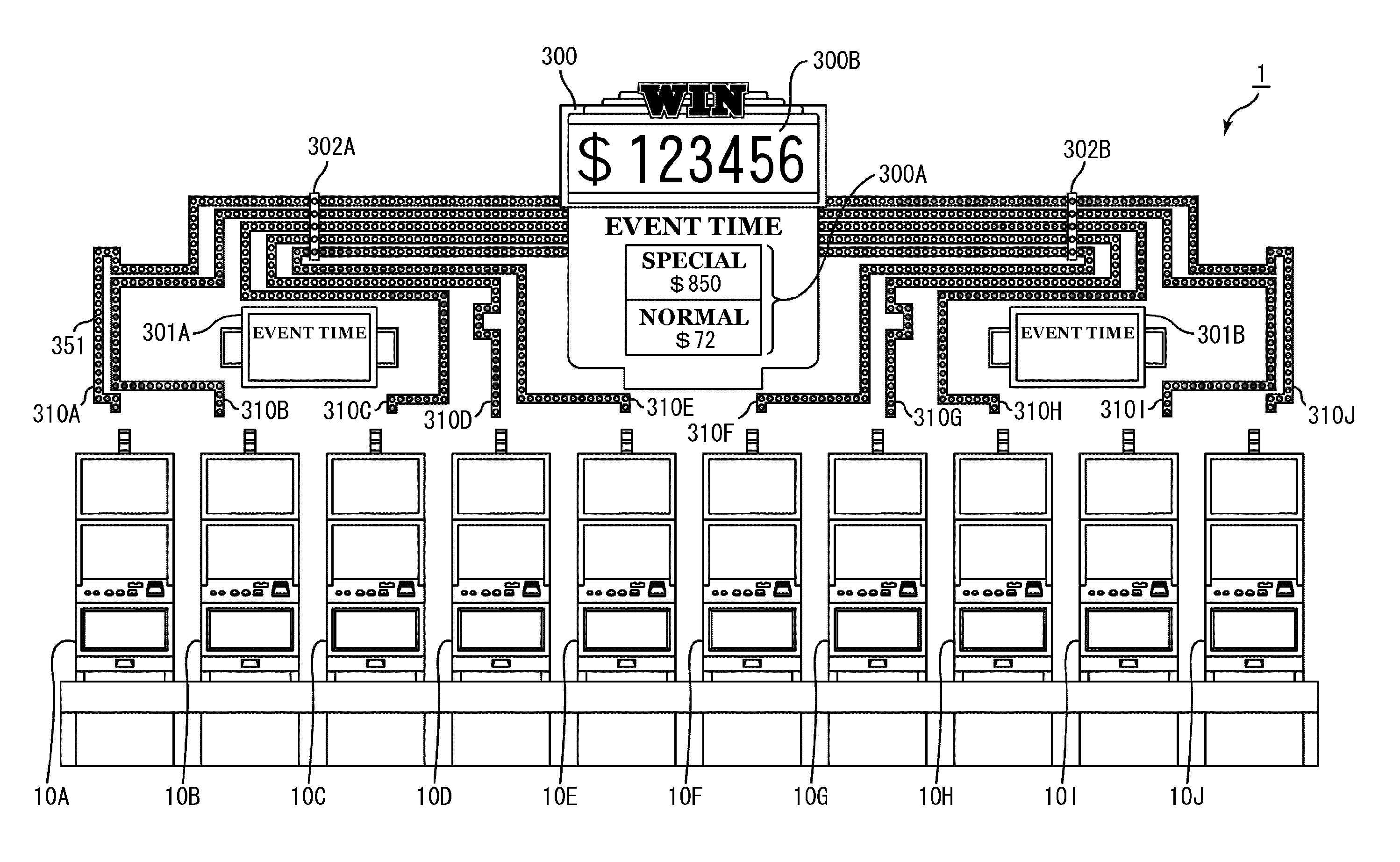
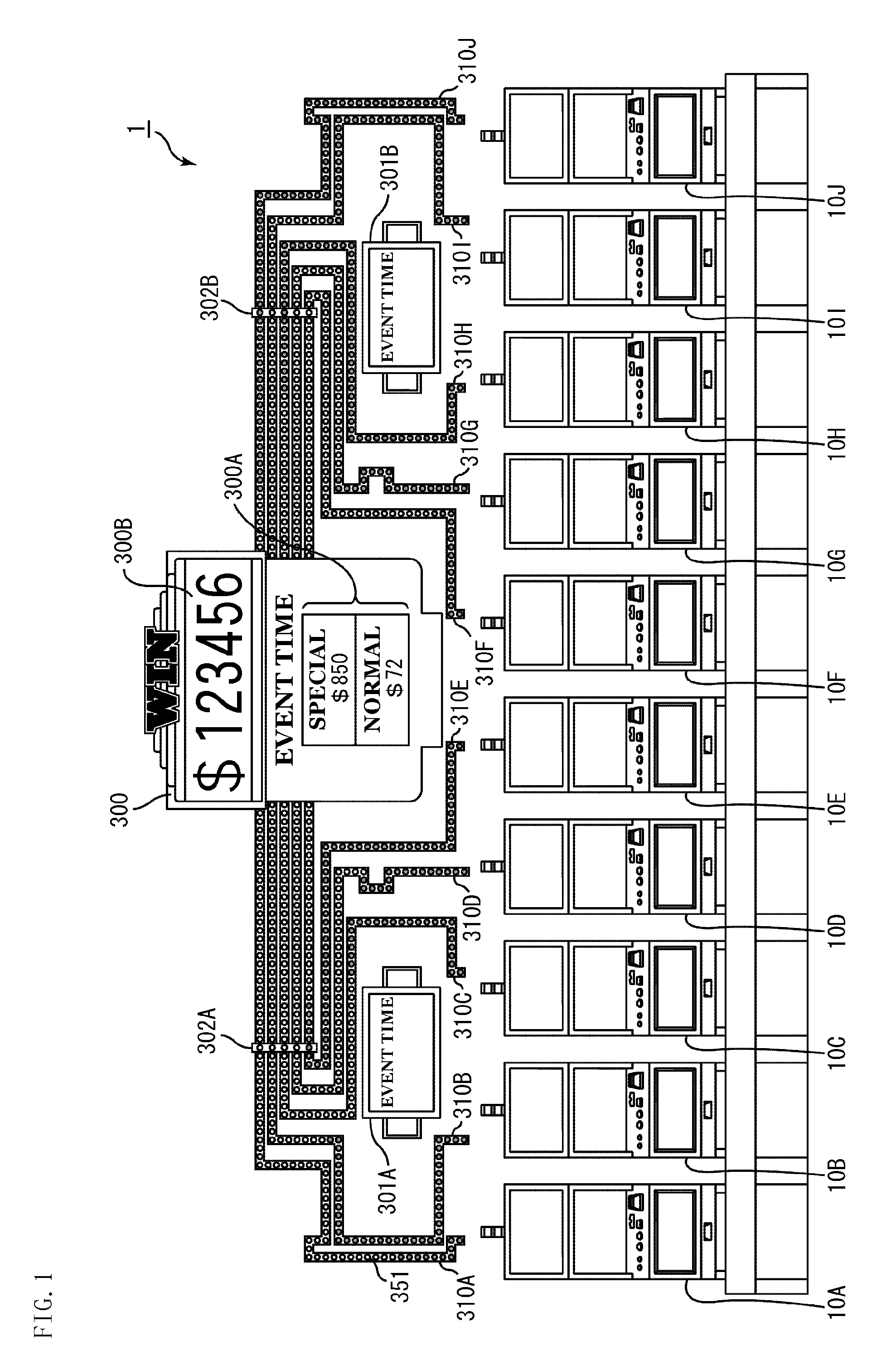
[0136]As illustrated in FIG. 1, a gaming system 1 includes a plurality of slot machines 10 (a slot machine 10A, a slot machine 10B, a slot machine 10C, a slot machine 10D, a slot machine 10E, a slot machine 10F, a slot machine 10G, a slot machine 10H, a slot machine 10I, and a slot machine 10J), a control device 200 (see FIG. 5), a common large display 300, and a plurality of common compact displays 301 (a common compact display 301A and a common compact display 301B), which are interconnected through a network.

[0137]Further, for the respective slot machines 10, there are provided coupling illumination lines 310 (a coupling illumination line 310A, a...

second embodiment

(Second Embodiment)

[0312]A second embodiment of the present invention is described based on the drawings.

[0313]At first, with reference to FIG. 22, there will be given a general description of the present embodiment.

[0314]FIG. 22 is a front view schematically illustrating a gaming system according to a second embodiment of the present invention.

[0315]As illustrated in FIG. 22, a gaming system 1001 includes a plurality of slot machines 1010 (a slot machine 1010A, a slot machine 1010B, a slot machine 1010C, a slot machine 1010D, a slot machine 1010E, a slot machine 1010F, a slot machine 1010G, a slot machine 1010H, a slot machine 1010I, and a slot machine 1010J), a control device 1200 (see FIG. 26), a common large display 1300, and a plurality of common compact displays 1301 (a common compact display 1301A and a common compact display 1301B), which are interconnected through a network.

[0316]Further, for the respective slot machines 1010, there are provided coupling illumination lines ...

third embodiment

(Third Embodiment)

[0507]A third embodiment of the present invention is described based on the drawings.

[0508]At first, with reference to FIG. 46, there will be given a general description of the present embodiment.

[0509]FIG. 46 is a front view schematically illustrating a gaming system according to a third embodiment of the present invention.

[0510]As illustrated in FIG. 46, a gaming system 2001 includes a plurality of slot machines 2010 (a slot machine 2010A, a slot machine 2010B, a slot machine 2010C,a slot machine 2010D, a slot machine 2010E, a slot machine 2010F, a slot machine 2010G, a slot machine 2010H, a slot machine 2010I, and a slot machine 2010J), a control device 2200 (see FIG. 50), a common large display 2300, and a plurality of common compact displays 2301 (a common compact display 2301A and a common compact display 2301B), which are interconnected through a network.

[0511]Further, for the respective slot machines 2010, there are provided coupling illumination lines 2310...


PUM


Abstract

According to a gaming system of the present invention, a part of the betted game media are cumulatively counted as the common-game cumulative value for the common game. When the common-game cumulative value has reached the specific value, the common game in which the game media in number corresponding to the specific value may be paid out is executed in each gaming machine. Based on the result of the common game in each gaming machine, a single gaming machine is determined and the game media in number corresponding to the specific value are paid out from the determined single gaming machine.

Description

CROSS-REFERENCE TO RELATED APPLICATIONS[0001]This application claims benefit of priority based on U.S. Provisional Patent Application No. 61 / 097,590 filed on Sep. 17, 2008, U.S. Provisional Patent Application No. 61 / 097,720 filed on Sep. 17, 2008 and U.S. Provisional Patent Application No. 61 / 097,459 filed on Sep. 16, 2008. The contents of this application are incorporated herein by reference in their entirety.BACKGROUND OF THE INVENTION[0002]1. Field of the Invention[0003]The present invention relates to a gaming system having a plurality of gaming machines linked by a network and a control method thereof.[0004]2. Discussion of the Background Art[0005]Conventionally, there exists a gaming system having a plurality of gaming machines linked by network as disclosed in: U.S. Pat. No. 6,068,553, U.S. Pat. No. 6,210,275, U.S. Pat. No. 6,224,484, US 2003 / 0236110-A1, US 2005 / 0079911-A1, US 2005 / 0119044-A1, US 2006 / 0205468-A1, US 2005 / 0187014-A1, US 2006 / 0287043-A1, US 2006 / 0073897-A1, US ...

Claims


Application Information

Patent Timeline
Patent Type & Authority Patents(United States)
IPC IPC(8): A63F13/00G07F17/32
CPCG07F17/3202G07F17/32G07F17/3258
Inventor KATO, YOICHI
Owner INTERBLOCK DOO
Why Eureka
Try Eureka