Tactile plate assembly

Active Publication Date: 2015-03-03
PIONEER DETECTABLE
View PDF15 Cites 14 Cited by
  • Summary
  • Abstract
  • Description
  • Claims
  • Application Information

AI Technical Summary

Benefits of technology

The invention is about a new kind of plate that can be embedded in pavements or concrete to provide a tactile surface for better navigation. The plate is held in place by interlocking brackets that are designed to anchor the plate to the material. This results in a strong connection that prevents the plate from moving or falling off. The brackets also allow for the plate to be placed in hot asphalt, where it can cool and harden to securely attach to the pavement. Overall, this invention makes it easier to create tactile surfaces in various materials and improves the user experience for people with disabilities.

Problems solved by technology

As is known to those skilled in the art, intersections between walkways and streets, railway crossings, etc. can present potential hazards.
Also, pedestrians who are hearing and / or vision impaired may not be aware of traditional safety warning devices such as crosswalk lights, painted markers, signs, or audible tones.
Thus, a previously-recognized problem has been alerting such pedestrians that they are approaching intersections where automobiles, trains, or other hazards may be present.
Such subassemblies typically are not interconnected and, thus, may become misaligned with one another either during installation or after.
Prior tactile plate assemblies could not be used in conjunction with asphalt as they tend to move out of position and / or bend when the asphalt is compressed.
Heretofore, these requirements have not been fully met without incurring various disadvantages.
These previous attempts remain deficient in addressing the issue of installing a warning device into curing asphalt as well as allowing an installer to effectively connect multiple warning devices to one another in an efficient manner.

Method used


Image

  • Tactile plate assembly
  • Tactile plate assembly
  • Tactile plate assembly

Examples


Embodiment Construction

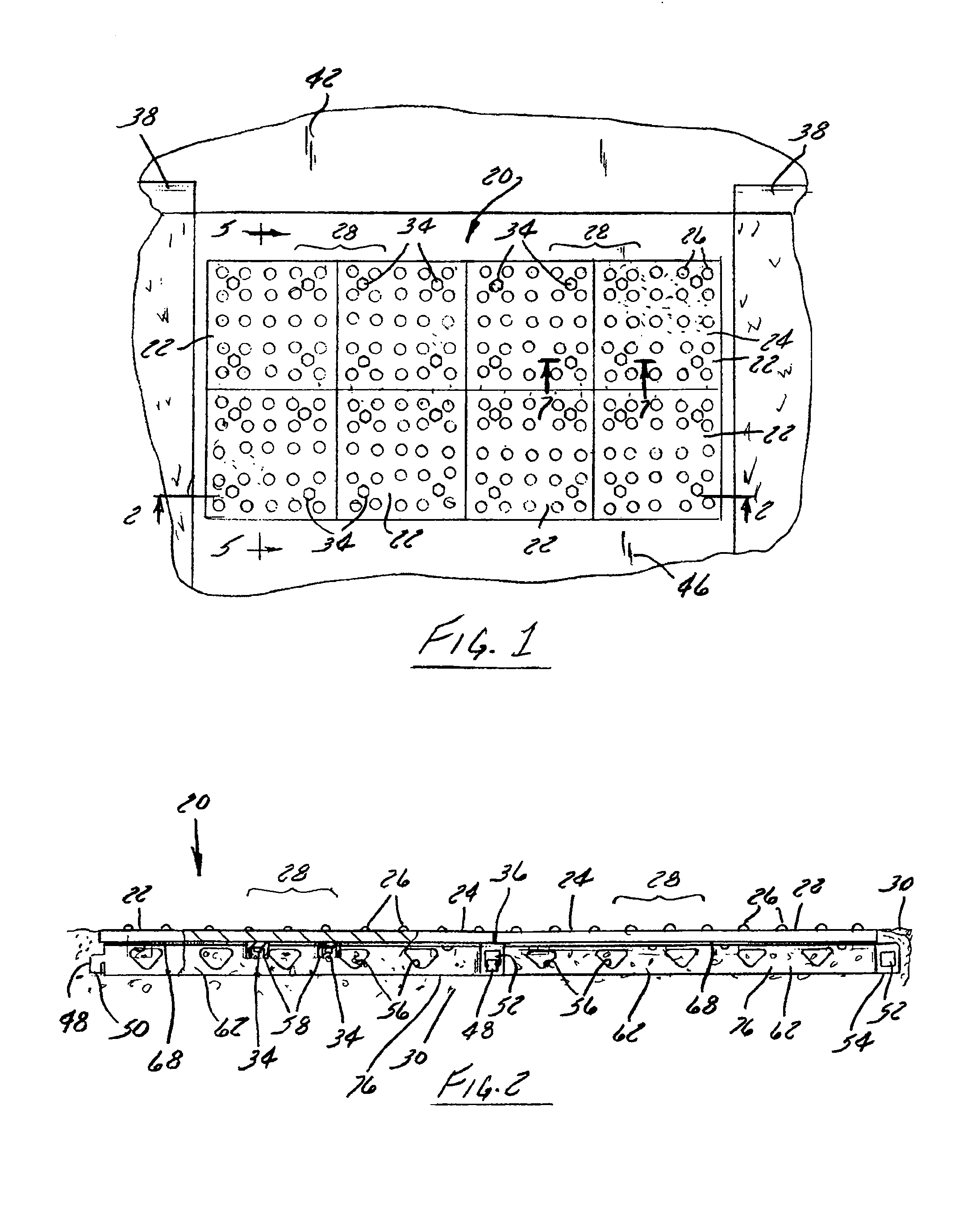
[0036]As shown in FIG. 1, a tactile plate assembly 20 constructed in accordance in a first embodiment of the invention is installed in a substrate in the form of a walkway 46 such as sidewalk. Typically, the tactile plate assembly 20 is positioned in the walkway 46 proximate to a street 42 and just before the street curb 38. The walkway 46 of this embodiment is formed from concrete. As shown in FIGS. 1 and 2, the tactile plate assembly 20 lies substantially flush with the surface of the surrounding walkway 46.

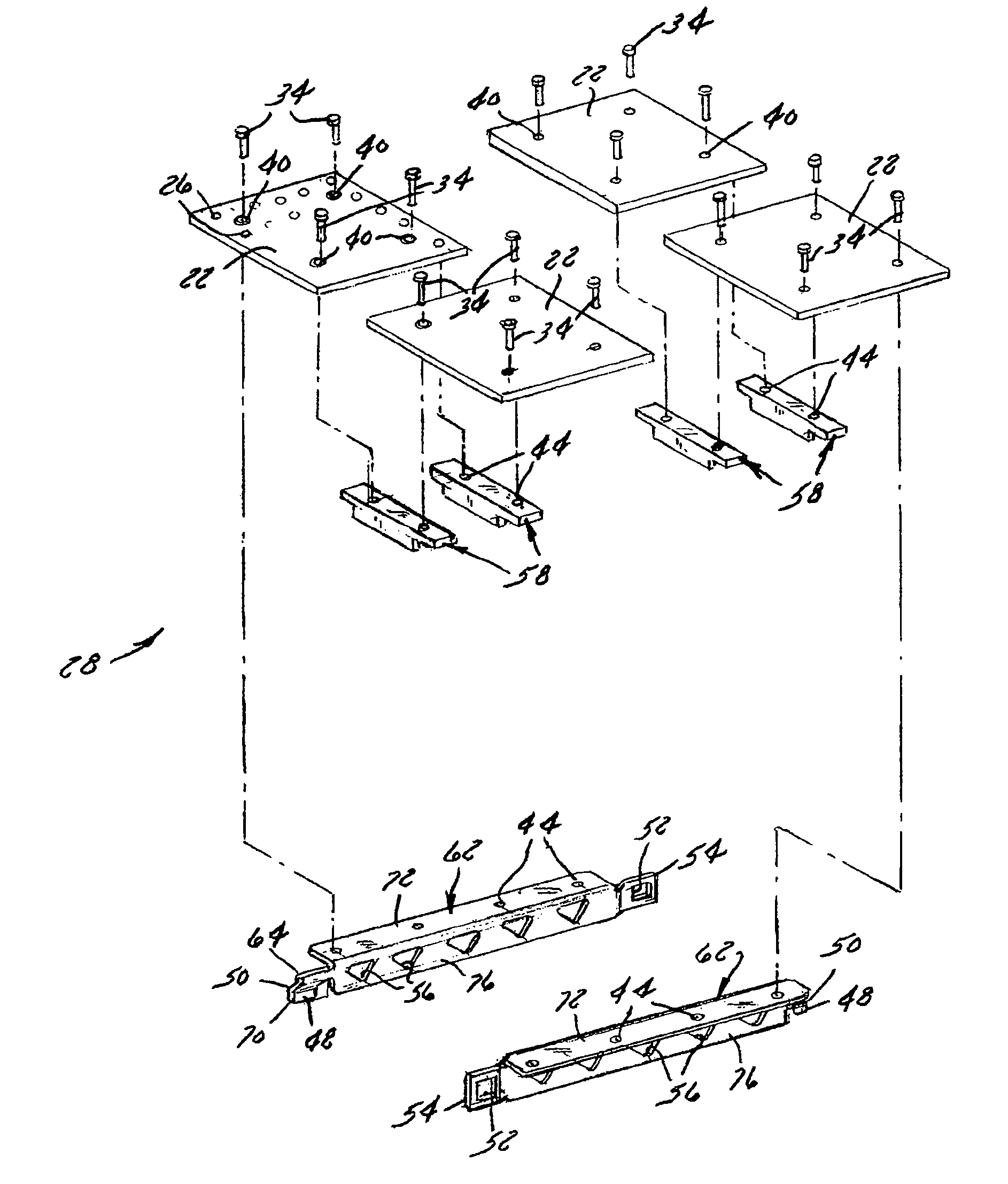
[0037]The tactile plate assembly 20 illustrated in FIG. 1 is composed of two subassemblies 28 interlocked together and then anchored in the walkway 46. Each subassembly 28 has a plurality of interconnected tactile plates 22. In the illustrated embodiment, each subassembly 28 has four tactile plates 22 coupled to one another by at least one laterally-extending connecting bracket 58 and at least one longitudinally interlocking bracket 62. The longitudinally extending interlocking...


PUM


Abstract

A tactile plate assembly used as a tactile warning device on walkways comprises a plurality of tactile plates with texture for providing tactile awareness. A connecting bracket attaches first and second tactile plates to each other to form a pair of tactile plates. Interlocking brackets, having first and second ends, attach two pairs of tactile plates together, forming a tactile plate subassembly. The interlocking brackets each includes a first end with a tab extending at an angle and a second end with a hole. The interlocking brackets can mate with one another to allow connection of multiple tactile plate subassemblies together. The interlocking brackets include multiple holes of sufficient size to allow a substrate such as concrete or asphalt to flow therethrough to anchor the tactile plate assembly in place. The connecting brackets may also include similar holes of sufficient size to allow a substrate to flow therethrough.

Description

BACKGROUND OF THE INVENTION[0001]1. Field of the Invention[0002]The present invention relates to tactile plate assemblies used in walkways to alert pedestrians, including those with vision disabilities, of an upcoming intersection or other potentially dangerous area. The present invention also relates to brackets used to secure the individual tactile plates of a tactile plate assembly to the underlying substrate as well as to each other.[0003]2. Discussion of the Related Art[0004]As is known to those skilled in the art, intersections between walkways and streets, railway crossings, etc. can present potential hazards. Awareness of impeding traffic is very important for a pedestrian attempting to walk across or otherwise traverse such an area. Also, pedestrians who are hearing and / or vision impaired may not be aware of traditional safety warning devices such as crosswalk lights, painted markers, signs, or audible tones. Thus, a previously-recognized problem has been alerting such pede...

Claims


Application Information

Patent Timeline
IPC IPC(8): E01C11/02E01C5/00
CPCA61H3/066E01C5/001E01C9/00E01C11/00E01C11/24E01C13/04E01C15/00G08B6/00
Inventor BUB, WARREN
Owner PIONEER DETECTABLE
Why Eureka
Try Eureka