Liquid ejecting apparatus
a technology of ejecting apparatus and liquid, which is applied in the direction of printing, etc., can solve the problem that the movement amount of the lock lever cannot be selectively increased
- Summary
- Abstract
- Description
- Claims
- Application Information
AI Technical Summary
Benefits of technology
Problems solved by technology
Method used
Image
Examples
first embodiment
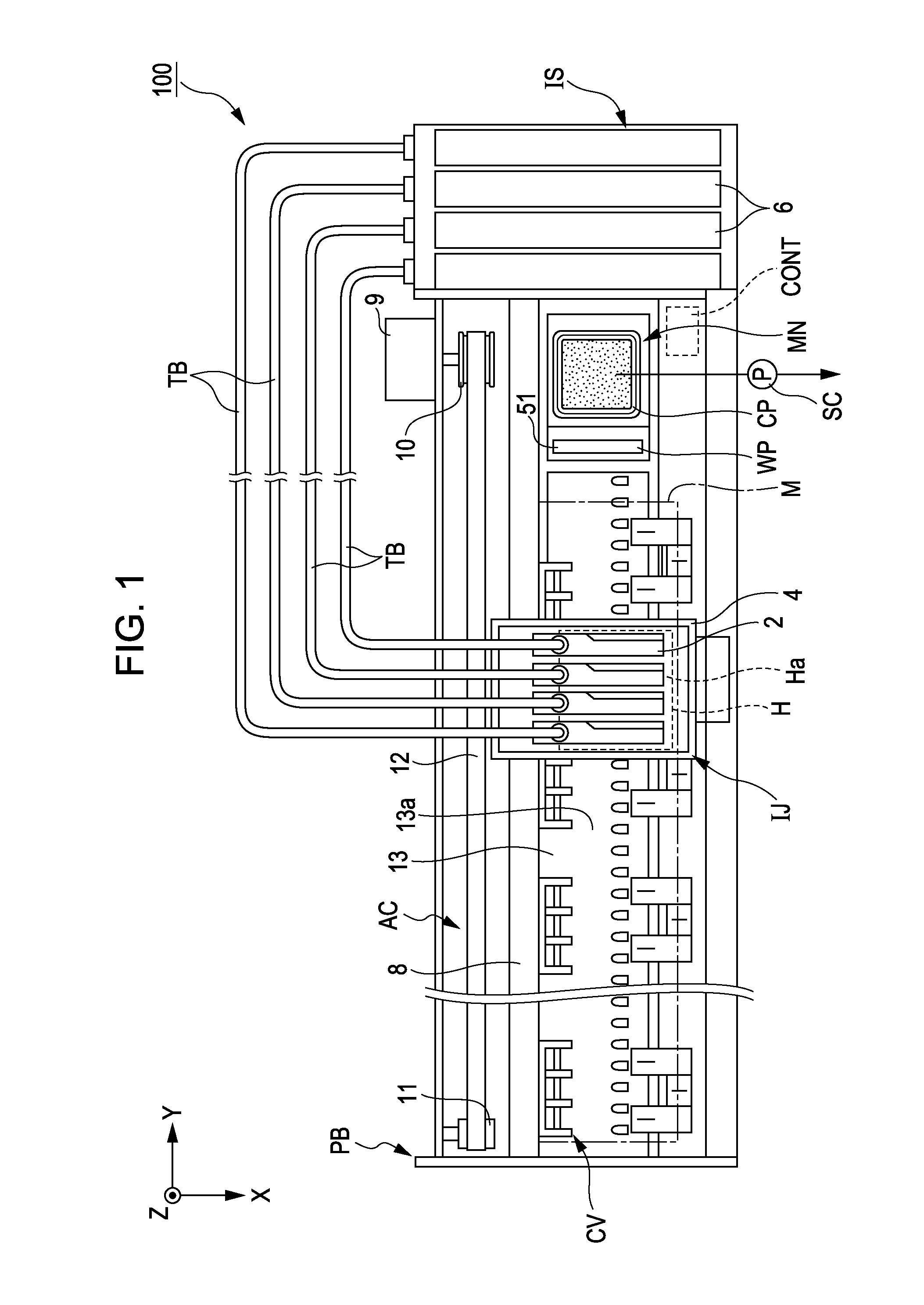
[0029]FIG. 1 is a diagram illustrating a schematic configuration of a printer 100 according to the present embodiment.
[0030]The printer 100 shown in FIG. 1 is an apparatus which transports a medium M with a sheet shape such as, for example, a paper sheet, or a plastic sheet and performs a printing process. The printer 100 includes a casing PB, an ink jet mechanism IJ which ejects ink on the medium M, an ink supply mechanism IS which supplies ink to the ink jet mechanism IJ, a transport mechanism CV which transports the medium M, a maintenance mechanism MN which performs a maintenance operation of the ink jet mechanism IJ, and a control device CONT which controls the respective mechanisms.
[0031]Hereinafter, an XYZ orthogonal coordinate system is set, and a positional relationship of each constituent element will be described by appropriately referring to the XYZ orthogonal coordinate system. In the present embodiment, for example, a transport direction of the medium M is indicated by...
second embodiment
[0073]Next, the second embodiment related to the printer 100 will be described. A difference between the present embodiment and the first embodiment is a peripheral structure of the maintenance mechanism MN, and the other configurations are common. Therefore, hereinafter, only a peripheral configuration of the maintenance mechanism MN will be described, and description of the other configurations will be omitted or be made briefly. In addition, the same constituent elements and members as in the first embodiment are given the same reference numerals and are described.
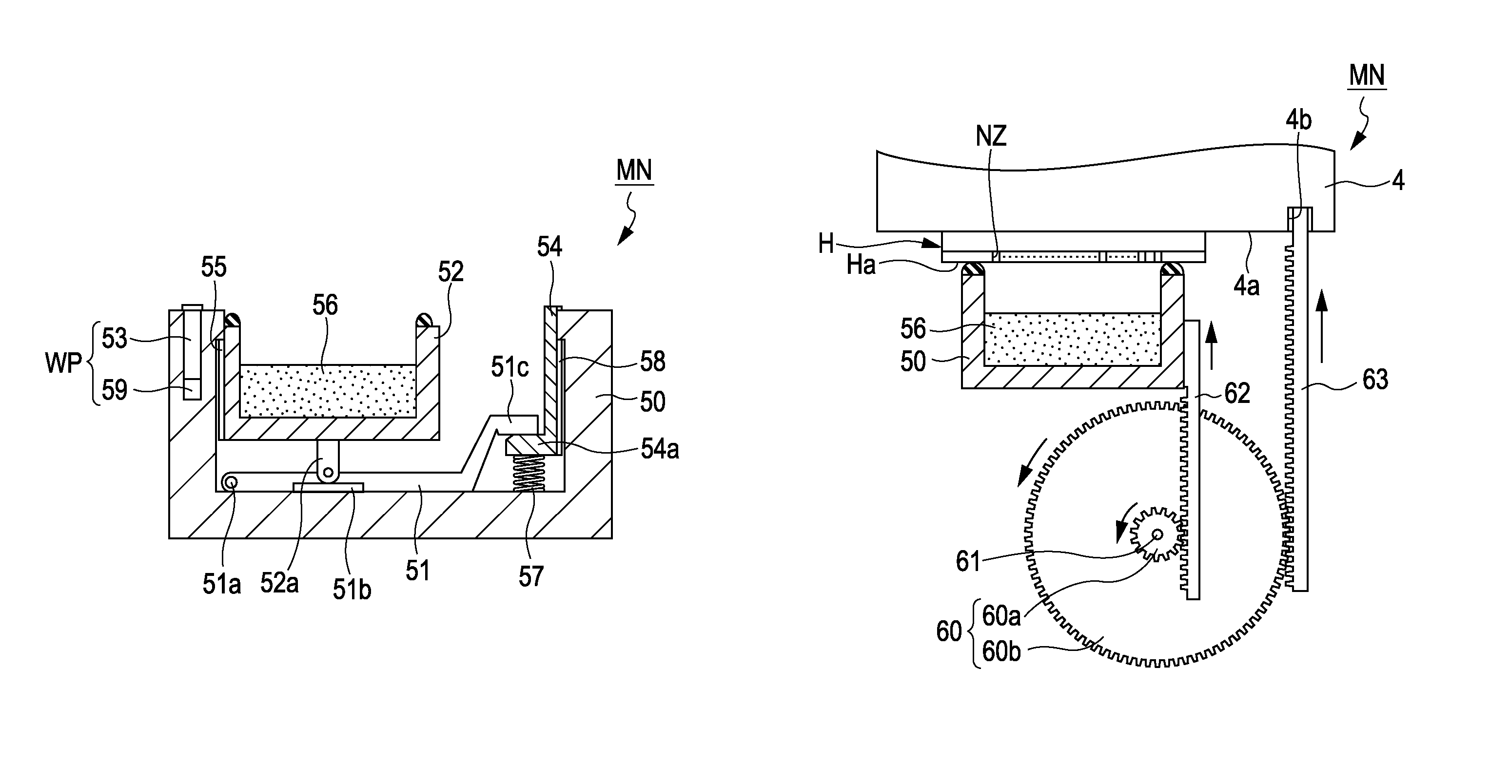
[0074]FIGS. 4A and 4B are cross-sectional views illustrating a configuration of a maintenance mechanism MN according to the present embodiment, where FIG. 4A shows a state in which a cap member is moved upward, and FIG. 4B shows a state in which the cap member is moved downward. The maintenance mechanism MN according to the present embodiment includes, as shown in FIGS. 4A and 4B, a gear portion 60 used as a movement me...
third embodiment
[0079]Next, the third embodiment related to the printer 100 will be described. A difference between the present embodiment and the first embodiment is a peripheral structure of the maintenance mechanism MN, and the other configurations are common. Therefore, hereinafter, only a peripheral configuration of the maintenance mechanism MN will be described, and description of the other configurations will be omitted or be made briefly. In addition, the same constituent elements and members as in the first embodiment are given the same reference numerals and are described.
[0080]FIGS. 5A and 5B are cross-sectional views illustrating a configuration of a maintenance mechanism MN according to the present embodiment, where FIG. 5A shows a state in which a lock member 154 is slightly moved upward, and FIG. 5B shows a state in which the lock member 154 is completely moved downward. The maintenance mechanism MN according to the present embodiment includes, as shown in FIGS. 5A and 5B, a lever me...
PUM
 Abstract
Description
Claims
Application Information
 - R&D
- Intellectual Property
- Life Sciences
- Materials
- Tech Scout
- Unparalleled Data Quality
- Higher Quality Content
- 60% Fewer Hallucinations
Browse by: Latest US Patents, China's latest patents, Technical Efficacy Thesaurus, Application Domain, Technology Topic, Popular Technical Reports.
© 2025 PatSnap. All rights reserved.Legal|Privacy policy|Modern Slavery Act Transparency Statement|Sitemap|About US| Contact US: help@patsnap.com


