Multiple-axis manual control device

a control device and multi-axis technology, applied in the direction of manual actuation control mechanisms, limiting/preventing/returning parts movement, instruments, etc., can solve the problems of relatively expensive and subject to malfunction, and achieve the effect of cost-effectiveness

Active Publication Date: 2015-03-03
W SMANN
View PDF21 Cites 0 Cited by
  • Summary
  • Abstract
  • Description
  • Claims
  • Application Information

AI Technical Summary

Benefits of technology

[0003]A manual control device of the generic type is known from U.S. Pat. No. 4,555,960. The manual control device described therein is constructed as a 6-axis control stick for an aircraft. An actuation cap of the control stick can be moved relative to a base member about or along six different movement axes. In particular, the actuation member is supported at one end of a switching rod for pivoting about two actuation member pivot axes and the switching rod itself is supported on the base member for pivoting about two further switching rod pivot axes. Owing to the spatial separation of the bearing for the actuation member pivot axes and for the switching rod pivot axes, they can be readily actuated independently of each other by an operator.
[0012]A configuration of the resilient elements as axial resilient elements, in particular as compression and / or as resilient elements has been found to be advantageous in practice. A variant of the invention in which the resilient elements are constructed as helical compression springs is distinguished as particularly simple and cost effective.
[0013]Particularly favourable conditions are produced when the clamping axes or resilient axes of the resilient elements extend parallel with the longitudinal axis of the switching rod and consequently perpendicularly relative to the actuation member pivot axis associated therewith. In this instance, it should be taken into consideration that a redirection of the actuation member about the actuation member pivot axis starting from the rest position through an angle of up to 20° is sufficient to carry out conventional control measures. In this angular range, a redirection of the actuation member about the actuation member pivot axis which extends perpendicularly relative to the longitudinal axis of the switching rod primarily brings about a displacement of the abutment faces for the resilient elements along the longitudinal axis of the switching rod. It is therefore particularly advantageous when the clamping axes of the resilient elements extend parallel with the longitudinal axis of the switching rod and the resilient elements can thereby absorb a main component of the displacement of the abutment faces for the resilient elements along their clamping axes.
[0014]The advantages of the restoring means constructed according to the invention set out above and described below are obtained in particular when two actuation member pivot axes are provided and there are associated with both actuation member pivot axes two resilient elements which are each arranged in pairs radially opposite each other relative to the longitudinal axis of the switching rod. A symmetrical and robust arrangement of the restoring means is produced on the whole.
[0015]In the case of a particularly preferred embodiment of the invention, all the actuation member movement axes and switching rod movement axes are each provided with separate restoring means. The restoring forces which can be produced by the restoring means are preferably adapted to each other in such a manner that the risk of unintentionally actuating one movement axis when actuating another is reduced. To this end, the restoring forces which can be felt by the operator on the actuation member are at least partially of different magnitudes, for example, the restoring forces for the actuation member pivot axes are noticeably smaller than those for the switching rod pivot axes. In particular, the restoring forces which are produced when an actuation member is pivoted about an actuation member pivot axis are significantly smaller than the restoring forces which are produced when the actuation member is redirected about a switching rod pivot axis which is parallel at least in the rest position of the actuation member.

Problems solved by technology

The restoring means of the control stick according to U.S. Pat. No. 4,555,960 are relatively costly and subject to malfunction.

Method used


Image

  • Multiple-axis manual control device
  • Multiple-axis manual control device
  • Multiple-axis manual control device

Examples


Embodiment Construction

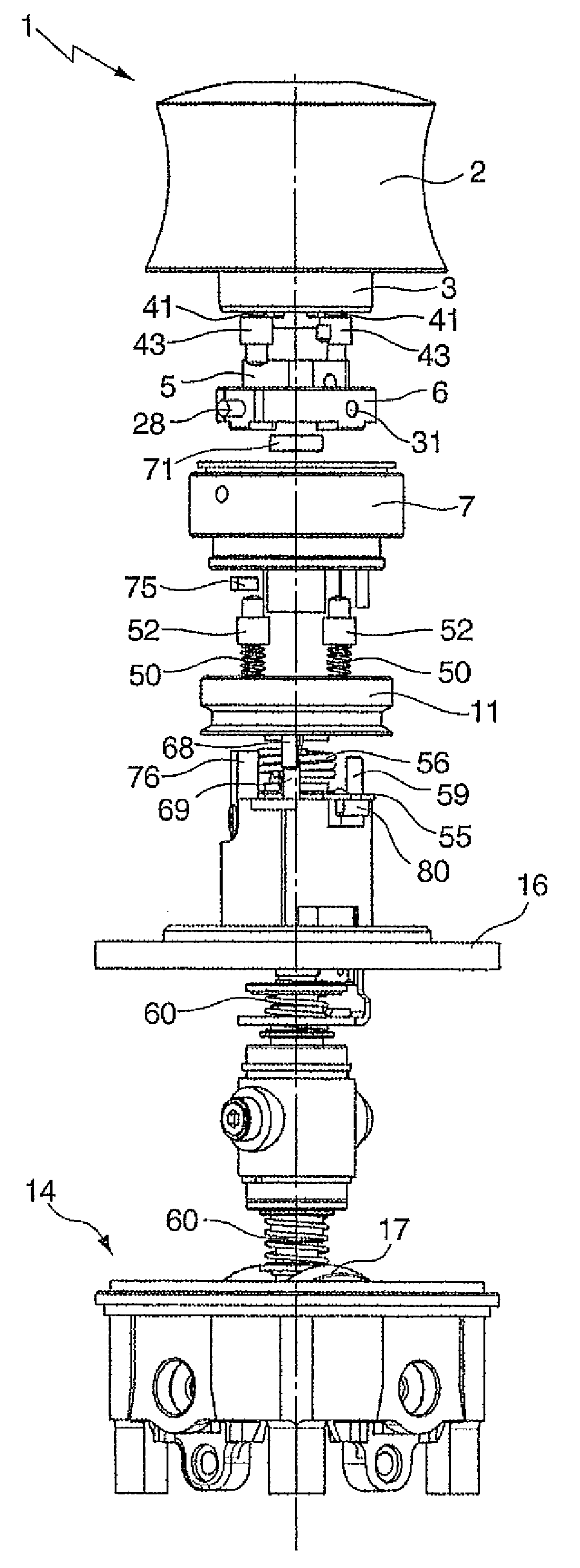
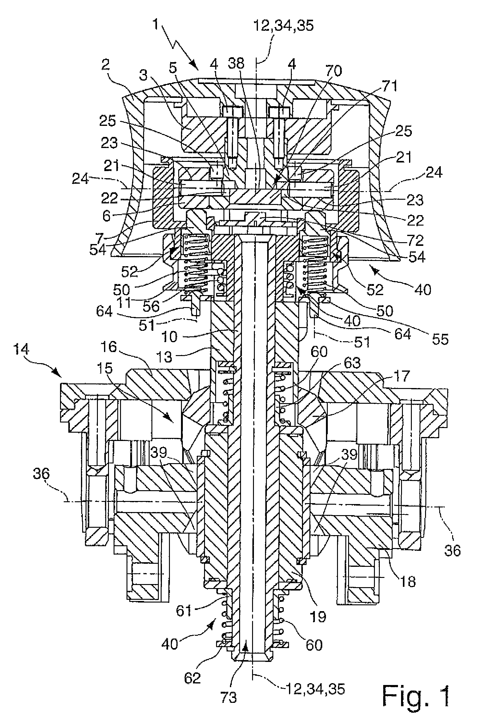
[0023]FIG. 1 is a sectioned illustration of a manual control device 1. The manual control device 1, also referred to as a composite drive, serves to control, for example, handling installations, cranes, vehicles, aircraft, etcetera. The manual control device 1 is provided with an actuation member 2 which is constructed as an actuation cap. The actuation member 2 is placed on a fixing plate 3 and secured at that location by means of a screw which is not illustrated. The fixing plate 3 is itself securely connected to an actuation member articulation piece 5 by means of screws 4. The actuation member articulation piece 5 is surrounded by a bearing ring 6, which itself is arranged in an actuation member receiving sleeve 7.

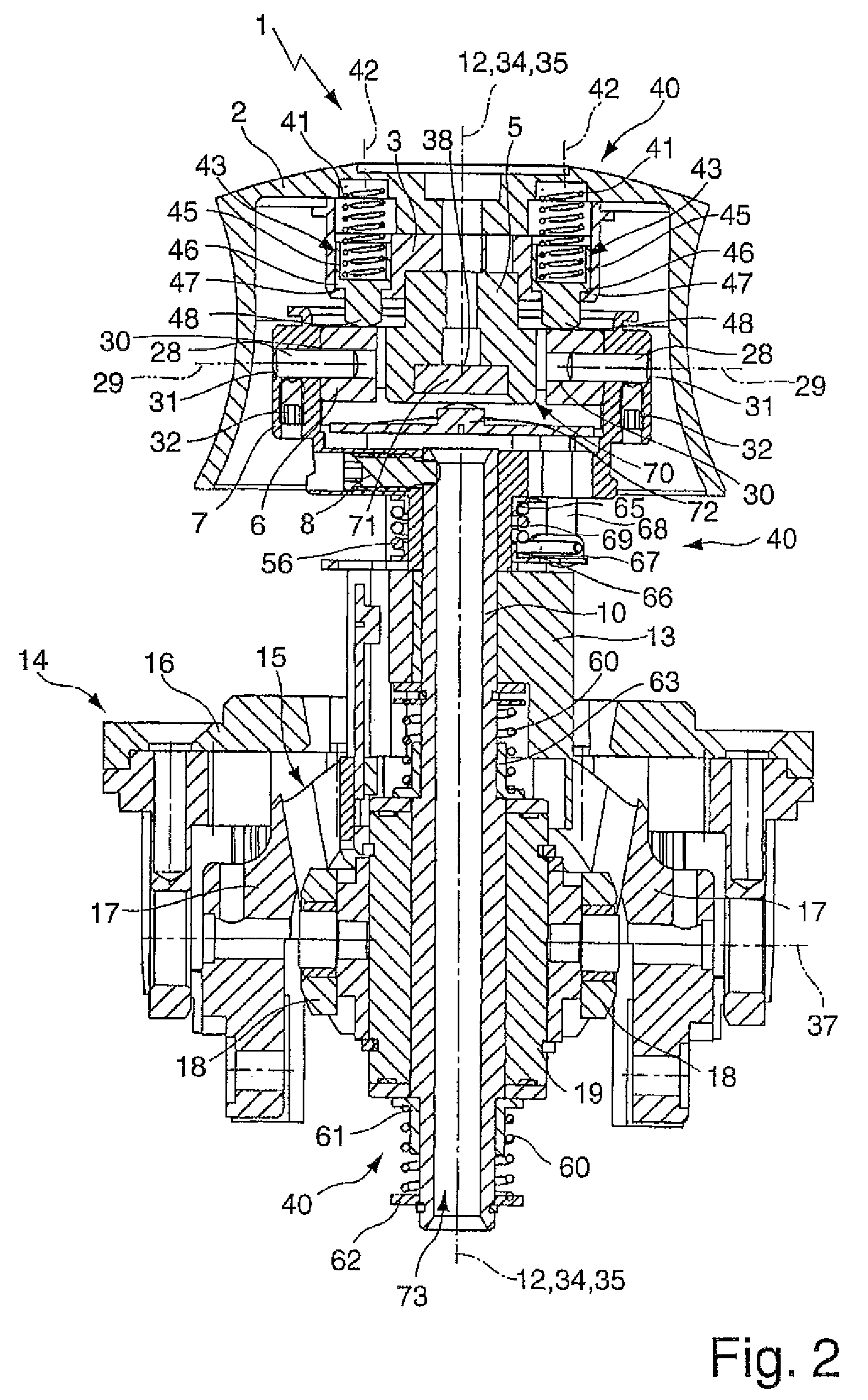
[0024]The actuation member receiving sleeve 7 is fitted at one end of a switching rod 10 in a rotationally secure and axially non-displaceable manner. A grub screw 8 (FIG. 2) serves to secure the actuation member receiving sleeve 7 to the switching rod 10. A centering ...


PUM


Abstract

A manual control device includes an actuation member which is supported on a switching rod for pivoting about at least one actuation member pivot axis which extends perpendicularly to the longitudinal axis of the switching rod. Furthermore, the switching rod is movably supported relative to a base member of the manual control device about or along a plurality of switching rod movement axes, there being provided restoring means, by means of which the actuation member which has been redirected out of a rest position about the actuation member pivot axis can be restored to the rest position. The restoring means have at least two resilient elements which are active counter to redirection of the actuation member from the rest position about the actuation member pivot axis and which are arranged radially opposite each other relative to the longitudinal axis of the switching rod.

Description

[0001]The invention relates to a manual control device which has an actuation member which is supported on a switching rod for pivoting about at least one actuation member pivot axis which extends perpendicularly to the longitudinal axis of the switching rod, the switching rod being movably supported relative to a base member of the manual control device about or along a plurality of switching rod movement axes, and there being provided restoring means, by means of which the actuation member which has been redirected out of a rest position about the actuation member pivot axis can be restored to the rest position.[0002]Such manual control devices are used, for example, for controlling handling installations, cranes, vehicles, aircraft, etcetera. They are sometimes also referred to as composite drives and may be constructed as control sticks or joysticks. The actuation member of the manual control device, for example, an actuation cap, a handle, etc. is supported for movement about a...

Claims


Application Information

Patent Timeline
Patent Type & Authority Patents(United States)
IPC IPC(8): G05G9/047G05G5/05
CPCG05G9/047G05G5/05Y10T74/20201
Inventor SCHULEIN, GERHARDEHRENSPERGER, ALWIN
Owner W SMANN
Why Eureka
Try Eureka