Card edge connector with floating metal member

a metal member and edge connector technology, applied in the direction of coupling device connection, coupling parts engagement/disengagement, electrical equipment, etc., to achieve the effect of improving the welding condition of metal members

Active Publication Date: 2015-02-24
HON HAI PRECISION IND CO LTD
View PDF34 Cites 2 Cited by
  • Summary
  • Abstract
  • Description
  • Claims
  • Application Information

AI Technical Summary

Benefits of technology

[0006]An object of the present invention is to provide a card edge connector to improve welding condition of metal members.
[0007]In order to achieve above-mentioned object, a card edge connector includes an insulative housing, a plurality of conductive terminals and a pair of metal members attached to the insulative housing. The insulative housing defining a pair of latching arms integrally extending forwardly from opposite ends thereof and a mounting slot below said each latching arm. Each metal member including a first metal member closely and vertical attached to the latching arm and a second metal member movably received in the mounting slot. Wherein the first metal member defines a stopping portion extending to the second metal member, the second metal member defines a solder portion and a stopped portion extending to the stopping portion, the stopping portion is located in front of the stopped portion in a front-to-rear direction, thereby the second metal member is prevent from forwardly departing from the mounting slot by the stopping portion of the first metal member, and the welding condition of the second metal member also has a certain improvement.

Problems solved by technology

It will produce a lot of heat which may cause distortion of the insulative housing due to the large number of the conductive terminals when the card edge connector is soldered to the circuit board, so that there may be a phenomenon of blank welding with the solder portion of the metal member welded.

Method used


Image

  • Card edge connector with floating metal member
  • Card edge connector with floating metal member
  • Card edge connector with floating metal member

Examples


Embodiment Construction

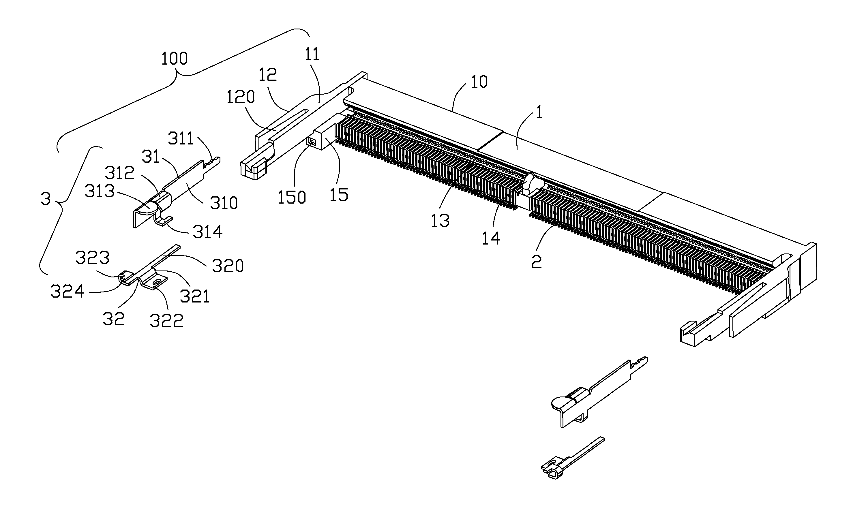
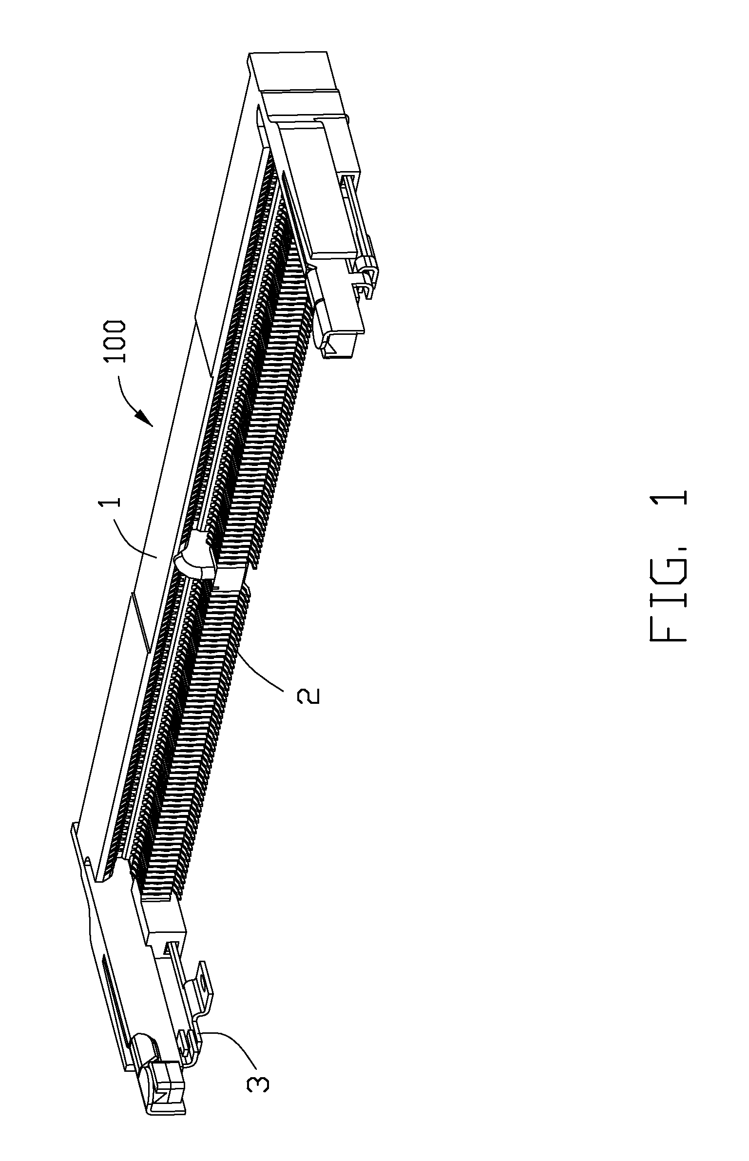
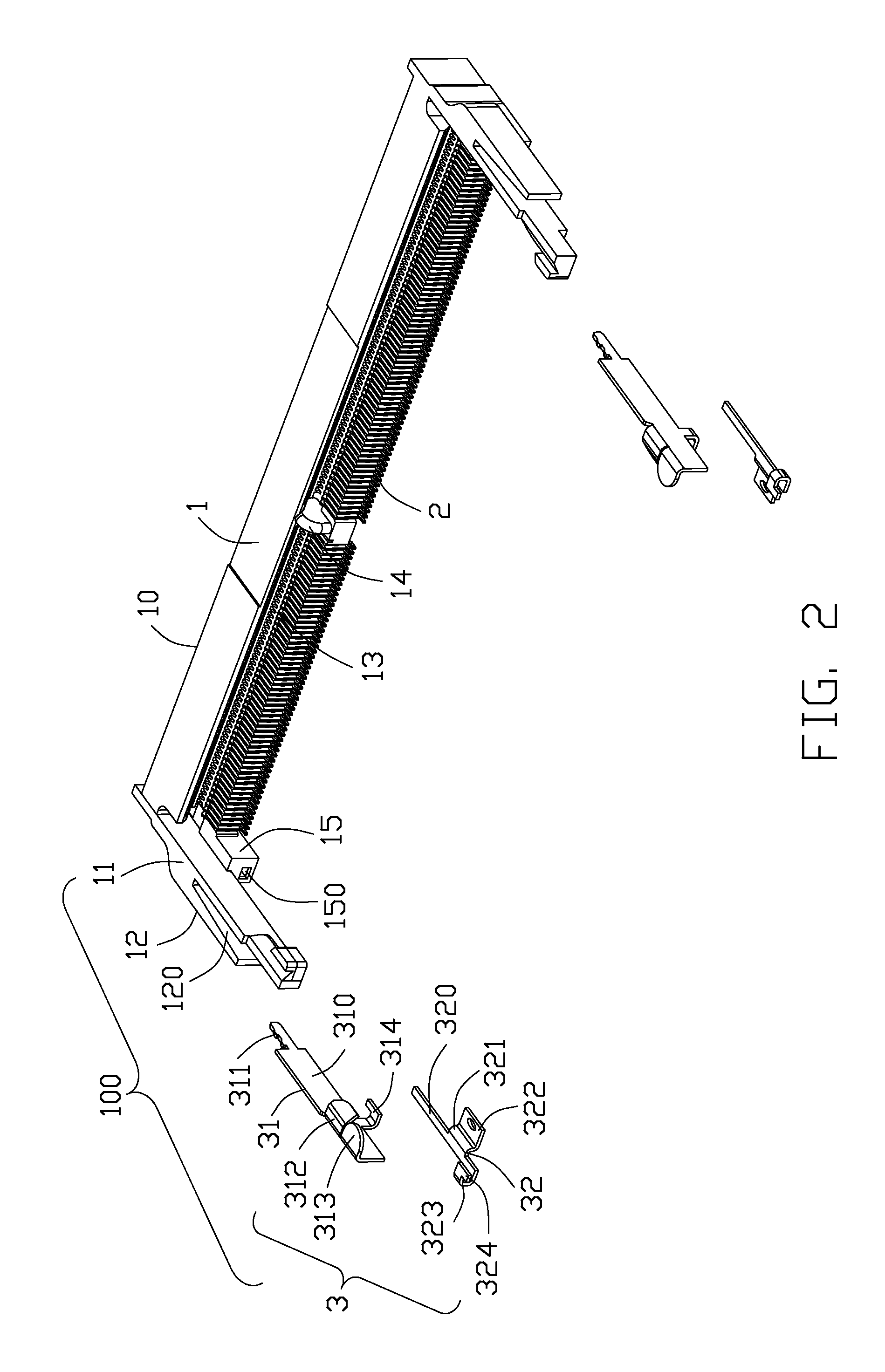
[0016]Reference will now be made to the drawing figures to describe a preferred embodiment of the present invention in detail. Referring to FIGS. 1 to 5 illustrate a card edge connector 100 for accommodating an electrical card and soldered on a motherboard of an electrical device in order to achieve the electronic transmission between the electrical card and the motherboard. The card edge connector 100 including an insulative housing 1, a plurality of conductive terminals 2 accommodated in the insulative housing 1 and a pair of metal members or fastening devices 3 mounted on the opposite ends of the insulative housing 1. It should be noted that the card edge connector of the present invention is a low profile card edge connector, such as a height of 4.0 mm, 2.5 mm, and so on. High profile card edge connectors have enough space to set metal members, while the low profile card edge connector is greater difficulty to set metal members due to space limitations.

[0017]The insulative housi...


PUM


Abstract

A card edge connector includes an insulative housing, a plurality of conductive terminals and a pair of metal members attached to the insulative housing. The insulative housing defining a pair of latching arms integrally extending forwardly from opposite ends thereof and a mounting slot below said each latching arm. Each metal member including a first metal member closely and vertical attached to the latching arm and a second metal member movably received in the mounting slot. wherein the first metal member defines a stopping portion extending to the second metal member, the second metal member defines a solder portion and a stopped portion extending to the stopping portion, the stopping portion is located in front of the stopped portion in a front-to-rear direction, thereby the second metal member is prevent from forwardly departing from the mounting slot by the stopping portion of the first metal member.

Description

BACKGROUND OF THE INVENTION[0001]1. Field of the Invention[0002]The present invention relates to a card edge connector, and more particularly to a card edge connector having a pair of metal members used for being mounted on a printed circuit board.[0003]2. Description of the Related Art[0004]China Pat. No. 100416938C issued on Sep. 3, 2008, discloses a card edge connector including: an insulative housing, a pair of latching arms extending forwardly from the longitudinal ends of the insulative housing and a plurality of conductive terminals accommodated in the insulative housing. Each of the latching arms defines a guide portion and a locking portion to provide a guide function and a locking function during an insertion of the electrical card module, respectively. Because of insufficient strength of the latching arm, each of the latching arms also defines a metal member in order to enhance the strength of the latching arm in the outside thereof The metal member includes an elongated ...

Claims


Application Information

Patent Timeline
Patent Type & Authority Patents(United States)
IPC IPC(8): H01R13/62H01R12/70H01R12/72
CPCH01R13/62H01R12/707H01R12/721
Inventor ZHU, JIAN-KUANGCHEN, DA-LEI
Owner HON HAI PRECISION IND CO LTD
Why Eureka
Try Eureka