
Head protection device and guiding bracket

a protection device and guiding bracket technology, applied in the direction of pedestrian/occupant safety arrangement, vehicle components, superstructure subunits, etc., can solve the problems of guiding wall, /b>cannot absorb the load of the passenger's head,

Active Publication Date: 2015-02-24
TOYOTA BOSHOKU KK
View PDF5 Cites 4 Cited by
  • Summary
  • Abstract
  • Description
  • Claims
  • Application Information

AI Technical Summary

Benefits of technology

[0007]In consideration of the current circumstances, an object of the present invention is to provide a head protection device and a guiding bracket that can smoothly guide an air bag to the vehicle cabin side while bearing a load caused by inflation of the air bag at expansion of the air bag, and can absorb a load of a passenger's head at a small collision causing no activation of an inflator.
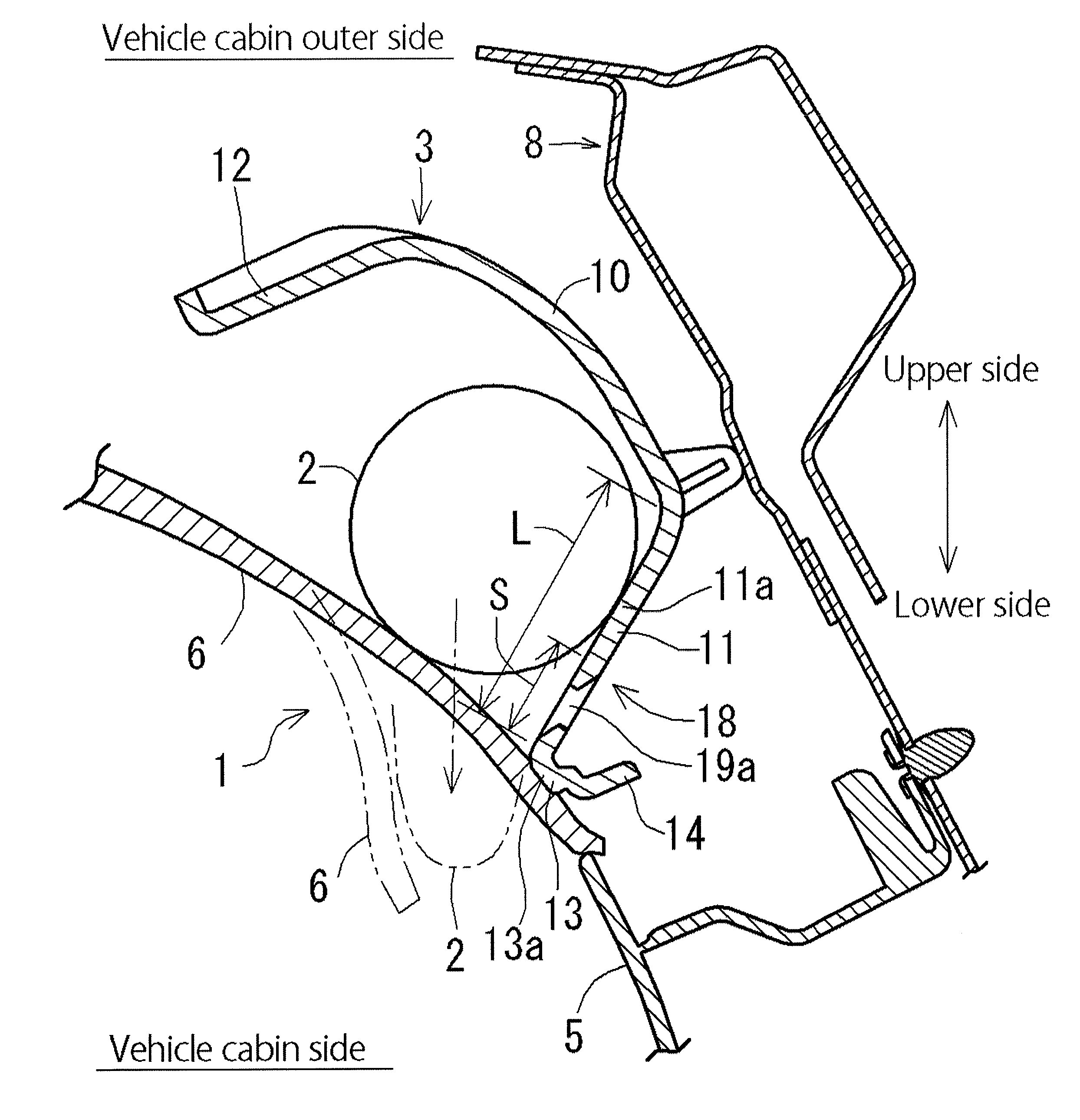
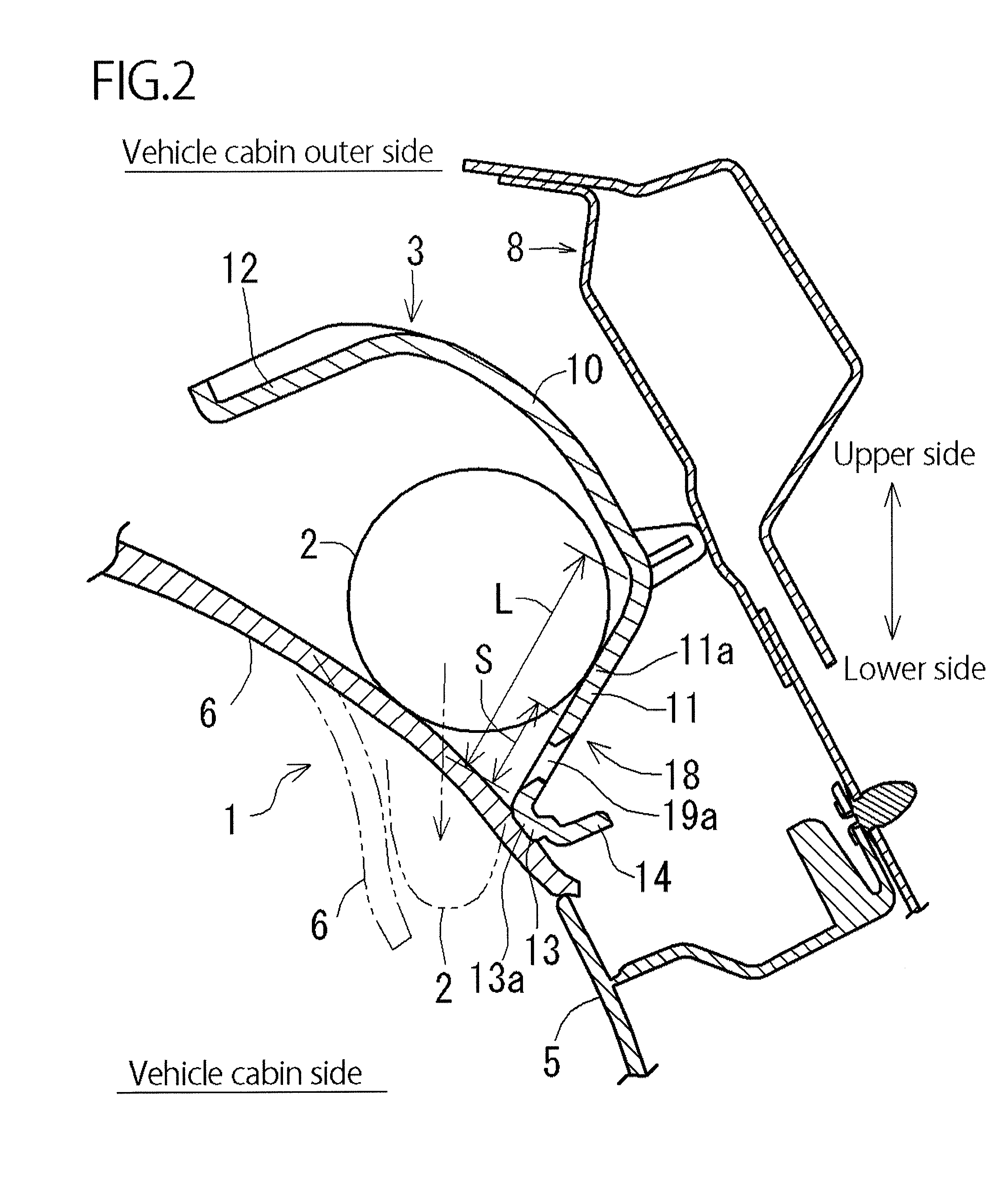
[0013]According to the head protection device in this embodiment, the guiding bracket includes the attachment surface that extends along the body panel in the vehicle vertical direction and has the attachment portion attached to the body panel, the guiding wall that extends from the lower end of the attachment surface toward the vehicle cabin side and has the support portion for supporting the air bag, and the contact portion that is coupled to the end of the guiding wall the vehicle cabin side and contacts the ceiling material. The weak portion deformed toward the vehicle cabin outer side by the load of the passenger's head at a collision causing no activation of the inflator is formed between the support portion of the guiding wall and the contact portion. Thus, at expansion of the air bag, the guiding wall can smoothly guide the air bag to the vehicle cabin side while bearing the load caused by inflation of the air bag. At a small collision causing no activation of the inflator, the weak portion is deformed toward the vehicle cabin outer side by the load from the vehicle cabin side, absorbing the load of the passenger's head.
[0014]In the case where the weak portion is formed near the contact portion of the guiding wall along the longitudinal direction of the vehicle, a distance between the weak portion and the stored air bag supported by the support portion is large, further suppressing the effect of the air bag on the weak portion at expansion of the air bag. Further, the weak portion can absorb the load more reliably.
[0016]In the case where the weak portion is formed of the through hole provided along the longitudinal direction of the vehicle, and the edge of the upper surface of the through hole in the vehicle cabin side has the inclined surface inclined toward the back surface of the guiding wall, at expansion of the air bag, it is prevented that the air bag caught with the through hole, and also prevented that the airbag is inhibited from expanding. Further, the weak portion can absorb the load more reliably.

Problems solved by technology

However, at small collision such that the inflator is not activated, the guiding wall 111 cannot absorb a load of the passenger's head, if any.

Method used


Image

  • Head protection device and guiding bracket
  • Head protection device and guiding bracket
  • Head protection device and guiding bracket

Examples


working example

[0036]A working example of the present invention will be specifically described with reference to drawings.

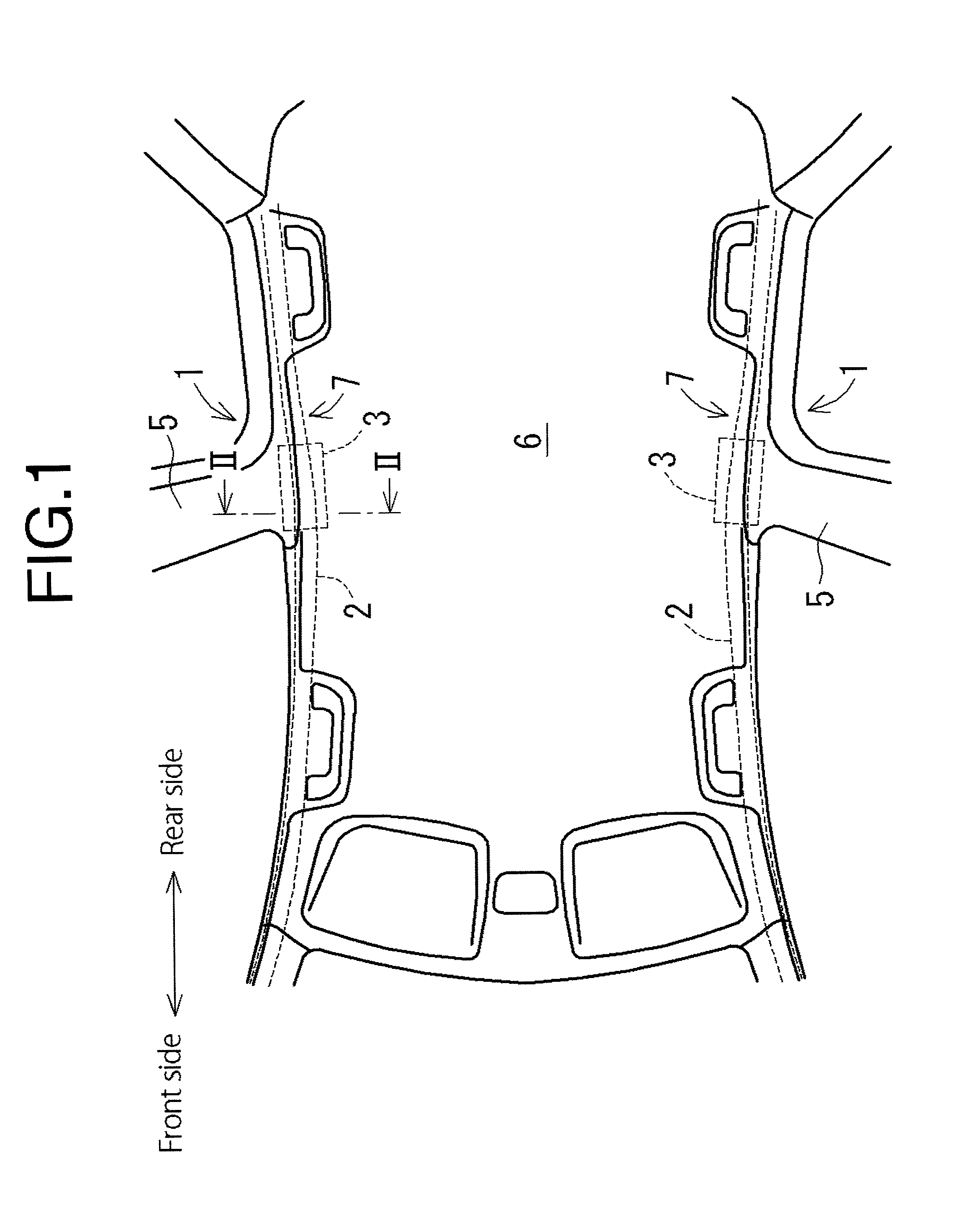
[0037]As shown in FIG. 1 and FIG. 2, a head protection device 1 in this working example includes an air bag (also referred to as “curtain shield air bag”) 2 and a guiding bracket 3. The airbag 2 is covered with an end of a ceiling material 6 arranged above a pillar 5 of a vehicle. Specifically, the air bag 2 is folded along a roof side 7 in a storage state. When an inflator (not shown) is activated to flow a gas into the air bag 2, the air bag 2 presses the ceiling material 6 from between the pillar 5 and the ceiling material 6 to open the ceiling material 6 to the vehicle cabin side, and expands and inflates downward (represented by a chain double-dashed line in FIG. 2). The guiding bracket 3 is covered with an end of the ceiling material 6 above the pillar 5. The guiding bracket 3 guides the airbag 2 expanded and inflated by the inflator to the vehicle cabin side. The air bag...


PUM


Abstract

A head protection device includes an air bag and a guiding bracket, and the guiding bracket includes an attachment surface that has an attachment portion attached to a body panel, a guiding wall that has a support portion for supporting the air bag, and a contact portion that is coupled to an end of the guiding wall in the vehicle cabin side and contacts a ceiling material. A weak portion deformed toward the vehicle cabin outer side by a load of a passenger's head at a collision causing no activation of an inflator is formed between the support portion of the guiding wall and the contact portion.

Description

CROSS-REFERENCE TO RELATED APPLICATIONS[0001]The present application claims priority under 35 U.S.C. §119 of Japanese Application No. 2012-234191 filed on Oct. 23, 2012, the disclosure of which is expressly incorporated by reference herein in its entirety.BACKGROUND OF THE INVENTION[0002]1. Field of the Invention[0003]The present invention relates to a head protection device and a guiding bracket, and in particular, to a head protection device and a guiding bracket that can smoothly guide an air bag to the vehicle cabin side while bearing a load caused by inflation of the air bag at expansion of the air bag, and can absorb a load of a passenger's head at small collision such that an inflator is not activated.[0004]2. Description of the Related Art[0005]A conventionally known head protection device includes an air bag and a guiding bracket (Refer to, for example, Japanese Unexamined Patent Publication No. 2006-175920). For example, as shown in FIG. 9, the patent document discloses a ...

Claims


Application Information

Patent Timeline
Patent Type & Authority Patents(United States)
IPC IPC(8): B60R21/213B60R21/232B60R13/02B60R21/00B60R21/04B60R21/16B60R21/214
CPCB60R21/213B60R21/214B60R13/0212B60R2021/0006B60R2021/0048B60R2021/161B60R2021/0442B60R2021/0435B60R2021/0414B60R2013/0287B60R21/232
Inventor UCHIDA, YASUNORI
Owner TOYOTA BOSHOKU KK
Learn More