
Apparatus for controlling depth/distance of sound and method thereof

a technology of depth/distance and apparatus, applied in the field of apparatus for controlling depth/distance of sound and method thereof, can solve the problems of insufficient development of applied examples of extracting and using stereoscopic information such as depth information and the like from stereoscopic images, and the effect of a technology of outputting sound suitable for a stereoscopic effect of a stereoscopic image is limited to how, and achieves more sense of realism

Active Publication Date: 2015-02-17
LG ELECTRONICS INC
View PDF6 Cites 0 Cited by
  • Summary
  • Abstract
  • Description
  • Claims
  • Application Information

AI Technical Summary

Benefits of technology

The present invention provides three effects or advantages. Firstly, it can output stereoscopic sound that matches the depth of the image, making it more realistic for the viewer. Secondly, it can output sound that matches the motion of objects in the image, giving it a more immersive feel. Lastly, it can make sound that reflects the depth change of objects in the image, giving the viewer a more harmonious and realistic experience.

Problems solved by technology

Yet, an applied example of extracting and using stereoscopic information such as depth information and the like from a stereoscopic image has not been sufficiently developed.
In case of a current 3D content, although individual effects of image and sound sensed by a viewer are represented well, an effect of a technology of outputting sound suitable for a stereoscopic effect of a stereoscopic image is limited to how well the stereoscopic effect reflects the sound when a producer produces a content.
Meanwhile, if is very difficult for a producer to have a sound reflect a stereoscopic effect of an object.
Moreover, despite the rapid spreading of stereoscopic image systems and the advent of a technology of outputting a conventional image as a stereoscopic image, it is difficult for sound to reflect a stereoscopic effect of an image in numerous contents.
However, even if this related art algorithm is used, sound at a physical speaker location is heard loud or weak only.

Method used


Image

  • Apparatus for controlling depth/distance of sound and method thereof
  • Apparatus for controlling depth/distance of sound and method thereof
  • Apparatus for controlling depth/distance of sound and method thereof

Examples


1st embodiment

1st Embodiment

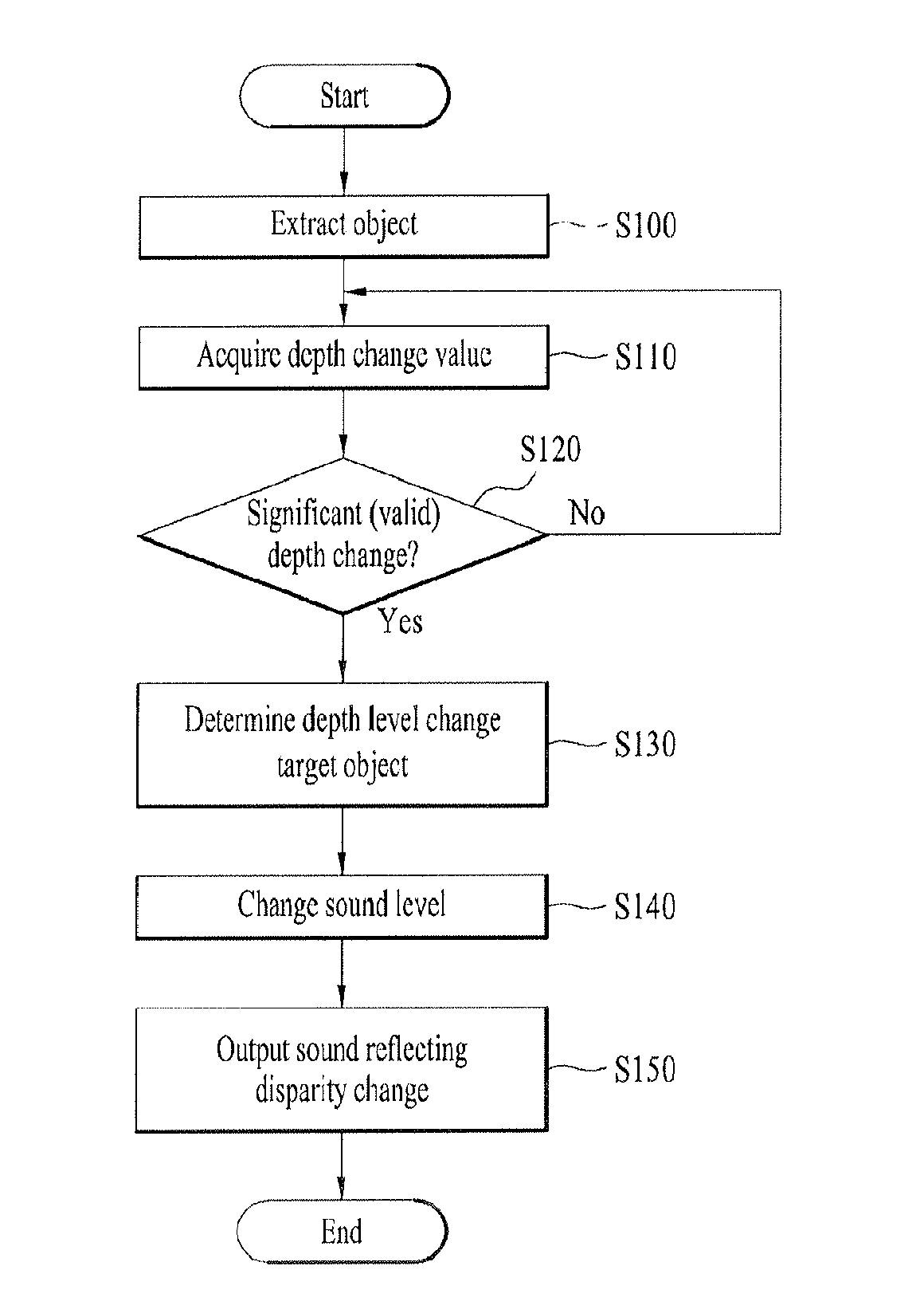
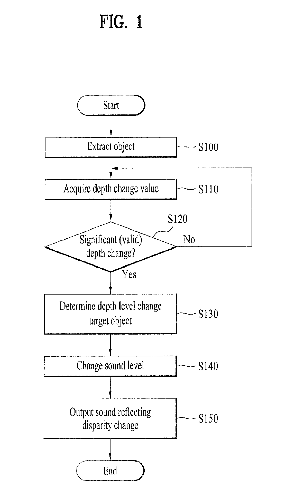
[0052]FIG. 1 is a flowchart for a method of controlling a depth / distance of sound corresponding to a disparity of a stereoscopic image object according to a 1st embodiment of the present invention. In the following description, a method of controlling a depth of sound is explained in detail with reference to FIG. 1.

[0053]Referring to FIG. 1, an image inputted from an image input source, and more particularly, a non-disparity image such as a stereo 2-channel image, a 1-channel image, a time-of-flight camera image and the like is converted to a disparity image. In this case, the disparity image means an image including pixels each of which has a level value (or a color) varying in accordance with an extent of disparity between right and left images or a depth.

[0054]Subsequently, using the disparity image, at least one object existing in the image is extracted [S100]. In particular, a specific region to be analyzed is extracted by extracting an object from an image. Throu...

2nd embodiment

2nd Embodiment

[0102]In the following description, a method of controlling a depth / distance of sound according to a 2nd embodiment of the present invention is explained in detail with reference to FIGS. 11 to 14.

[0103]FIG. 11 is a flowchart for a method of controlling a depth / distance of sound according to a 2nd embodiment of the present invention.

[0104]Referring to FIG. 11, in a method of controlling a depth / distance of sound according to a 2nd embodiment of the present invention, first of all, a disparity histogram indicating a weight per pixel / region in accordance with a depth / disparity is acquired from a binocular disparity image [S710].

[0105]For instance, a disparity map is extracted from a binocular disparity image, the extracted disparity map is divided into a plurality of screen regions w1 to w3, as shown in FIG. 12, and weights are then applied to a plurality of the screen regions, respectively. On the assumption that a center region of the screen is more important than the ...

3rd embodiment

3rd Embodiment

[0110]In the following description, a method of controlling a depth / distance of sound according to a 3rd embodiment of the present invention is explained in detail with reference to FIGS. 15 to 18.

[0111]FIG. 15 is a flowchart for a method of controlling a depth / distance of sound according to a 3rd embodiment of the present invention.

[0112]Referring to FIG. 15, in a method of controlling a depth / distance of sound according to a 3rd embodiment of the present invention, first of all, a disparity histogram indicating a weight per pixel / region in accordance with a depth / disparity is acquired from a binocular disparity image [S810]. The disparity histogram acquiring method is identical to the former acquiring method of the 2nd embodiment of the present invention.

[0113]Subsequently, as shown in FIG. 14, a disparity histogram per level interval is found in a manner of dividing a horizontal axis of all histogram intervals, i.e., an axis of depth as many as the number of desired...


PUM


Abstract

An apparatus for controlling depth / distance of sound and method thereof are disclosed, by which an audio signal can be outputted to correspond to a depth of an image, i.e., a disparity in displaying a stereoscopic image. The present invention includes extracting at least one object from an image, measuring a depth change value in accordance with a motion of the object within the image, and changing a depth / distance level of the sound based on the depth change value of the object.

Description

[0001]This application claims the benefit of the Korean Patent Application Nos. 10-2011-0024853, filed on Mar. 21, 2011 and 10-2011-0088372 filed on Sep. 1, 2011, which are hereby incorporated by reference as if fully set forth herein.BACKGROUND OF THE INVENTION[0002]1. Field of the Invention[0003]The present invention relates to an apparatus for controlling depth / distance of sound and method thereof. Although the present invention is suitable for a wide scope of applications, it is particularly suitable for outputting an audio signal corresponding to depth of an object existing in a binocular disparity image.[0004]2. Discussion of the Related Art[0005]Recently, the ongoing development of the related technology enables a technology of obtaining stereoscopic information of an object from a stereoscopic image to be applied to various fields of game, surveillance camera, vehicle camera and the like. Yet, an applied example of extracting and using stereoscopic information such as depth ...

Claims


Application Information

Patent Timeline
Patent Type & Authority Patents(United States)
IPC IPC(8): H04R5/00G06T7/20H04S1/00H04S3/00H04S7/00
CPCG06T7/2053H04S7/30G06T2207/10028H04S2400/11H04S2420/01H04S1/007H04S3/008H04S2420/07G06T7/254
Inventor JEONG, SANGOHKIM, HYUNSOOJEON, BYEONGMOONKIM, KYUWOONBHANG, JOONWON
Owner LG ELECTRONICS INC
Learn More