
Polymer vesicles for selective electromagnetic energy-induced delivery

a technology of selective electromagnetic energy and vesicles, which is applied in the direction of capsule delivery, microcapsules, pharmaceutical delivery mechanisms, etc., can solve the problems of inability to accurately target the target tissue, damage the surrounding tissue, and inability to focus the microwav

Active Publication Date: 2015-02-10
THE TRUSTEES OF THE UNIV OF PENNSYLVANIA
View PDF13 Cites 1 Cited by
  • Summary
  • Abstract
  • Description
  • Claims
  • Application Information

AI Technical Summary

Benefits of technology

The polymer vesicles provide targeted and selective delivery of therapeutic or diagnostic agents, minimizing damage to surrounding tissues and enhancing the precision of electromagnetic energy-induced release.

Problems solved by technology

The major drawback of the use of microwaves is that microwaves cannot be focused as they have long wavelengths, and therefore they tend to damage surrounding tissues.
In addition, microwaves indiscriminately heat up both the liposomes and the surrounding tissues, and since microwaves are non-visible electromagnetic energy they cannot be aimed at the target tissues accurately.
The drawback of employing lipid vesicles for intracorporeal delivery of therapeutic agents is that lipid vesicles lack strength and durability.

Method used


Image

  • Polymer vesicles for selective electromagnetic energy-induced delivery
  • Polymer vesicles for selective electromagnetic energy-induced delivery
  • Polymer vesicles for selective electromagnetic energy-induced delivery

Examples


example 1

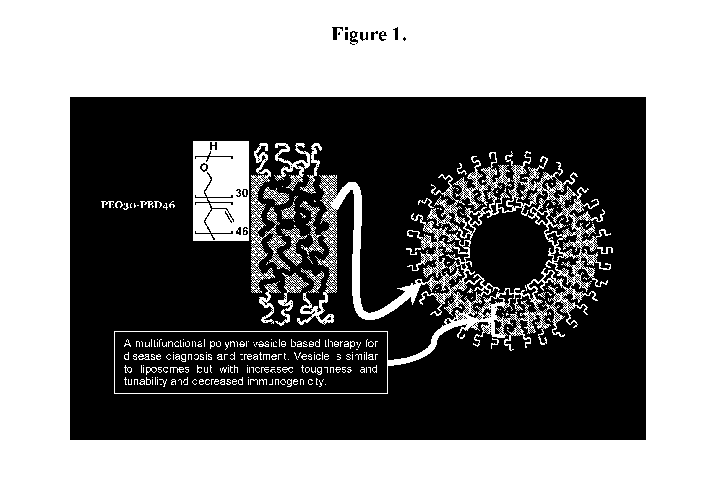
[0073]Polymersome Assembly. Thin films of polymer were created on roughened Teflon surfaces by depositing 200 μL of a 1 mM solution of OB29 with or without porphyrin dye at a 5:1 molar ratio (polymer:dye) in methylene chloride. Films were dried in a vacuum oven for 12 h and then hydrated with 1 or 2 mL of a 290 mOsm sucrose+PBS buffer with or without protein at 65° C. for 24 h. Vesicle solutions were vortexed after heating. Vesicles are depicted in FIG. 1.

example 2

[0074]Vesicle Separation. Vesicles were separated from free protein by diluting 500 μL polymer vesicle solution in 9.5 mL PBS+1% BSA. This solution was then placed on a 2 mL cushion of sucrose buffer+density gradient medium in a centrifuge tube. The tube was spun at 20,000 rpm for 1 h, and the resulting band of 500-1000 μL concentrated solution of vesicles was removed. Samples were then dialyzed into 290 mOsm PBS within 20,000 Da MWCO dialysis cassettes for 12 h at 4° C.

example 3

[0075]Chemical labeling of HSF, HSAF, BSA and Mb. The concentration of HSAF, BSA, or Mb was determined by UV-Vis spectroscopy (ε280=480,000 M−1cm−1 for HSAF,[2]ε280=44,300 M−1cm−1 for BSA, and ε280=15,400 M−1cm−1 for Mb). BSA required several FPLC size-exclusion purification steps to eliminate protein aggregates and fragments. The concentration of HSF was determined by Bradford assay. The Cy3 dye was used to label surface lysines on the protein, whereas BODIPY-FL labeled surface cysteines. The protein labeling protocols provided by the manufacturers were followed for both Cy3 and BODIPY-FL conjugations, with the following modifications. For the Cy3 labeling: i) 10 mg / mL protein in 290 mOsm PBS was used, ii) the conjugation reaction was carried out for 2-3 h, and iii) the labeled protein was separated from free dye with 290 mOsm sucrose+PBS buffer. For the BODIPY-FL labeling: i) 500-fold molar excess (20-fold per ferritin subunit) of TCEP was used, ii) 400-fold molar excess (17-fold ...


PUM

PropertyMeasurementUnit
timeaaaaaaaaaa
diametersaaaaaaaaaa
diametersaaaaaaaaaa

Abstract

Provided are polymer vesicles comprising polymersomes, a radiofrequency absorbing moiety, a protein or a polysaccharide associated with the inner leaflet of the membrane and a therapeutic or diagnostic cargo. The invention also concerns the use of these polymer vesicles for selective electromagnetic energy-induced delivery of therapeutic or diagnostic agents.

Description

CROSS REFERENCE TO RELATED APPLICATION[0001]This application claims the benefit of U.S. Provisional Application No. 61 / 100,472 filed Sep. 26, 2008, which is incorporated by reference herein in its entirety.STATEMENT OF FEDERALLY SPONSORED RESEARCH[0002]This invention was made with Government support under Grant Nos. NSF MRSEC DMR-0520020 (to Ivan J. Dmochowski, Daniel A. Hammer, and Michael J. Therien), NSF CAREER CHE-0548188 and NCRR 1S10-RR-021113-01 (to Ivan J. Dmochowski), and National Institutes of Health Grant Nos. R01CA115229 and EB003457 (to Michael J. Therien and Daniel A. Hammer). The Government has certain rights in this invention.FIELD OF THE INVENTION[0003]The invention pertains to polymer vesicles for selective electromagnetic energy-induced delivery of therapeutic and diagnostic agents.BACKGROUND OF THE INVENTION[0004]Polymersomes, 50 nm-50 μm diameter vesicles formed from amphiphilic block copolymers, have attracted much attention due to their superior mechanical sta...

Claims


Application Information

Patent Timeline
Patent Type & Authority Patents(United States)
IPC IPC(8): A61K8/64A61K8/90A61K9/00A61K9/107A61K9/127
CPCA61K9/0009A61K9/1075A61K9/1273
Inventor HAMMER, DANIEL A.DMOCHOWSKI, IVAN JULIANROBBINS, GREGORY PATRICKJIMBO, MASAYA S.THERIEN, MICHAEL J.KAMAT, NEHA P.
Owner THE TRUSTEES OF THE UNIV OF PENNSYLVANIA
Learn More