
Method for calibrating clinical chemistry instruments

a clinical chemistry and instrument technology, applied in the direction of instruments, liquid/fluent solid measurement, material analysis, etc., can solve the problems of instrument-to-instrument variability in sensitivity, not the general case, and the inability to hold centroids to such close tolerances

Active Publication Date: 2015-02-03
IDEXX LABORATORIES
View PDF2 Cites 4 Cited by
  • Summary
  • Abstract
  • Description
  • Claims
  • Application Information

AI Technical Summary

Benefits of technology

The present invention aims to provide a method for determining an offset that can be used to compensate for the wavelength variability of an object illuminating light source used in a clinical chemistry instrument. Another objective is to calibrate the instrument in a way that avoids the disadvantages of conventional calibration methods.

Problems solved by technology

This problem of instrument-to-instrument variability in sensitivity is especially prevalent with test slides or cuvettes containing chromophores with a narrow reflection density or absorbance band or a steep baseline in the region of the band.
If identical test samples were run on substantially identical calcium test slides, but on instruments with varying sensitivity to the complex, then otherwise uncompensated instruments with lower sensitivity would generally report lower calcium concentrations than those with higher sensitivity to the complex.
While for some LEDs, the emission band shape and centroid (or peak) wavelength characteristics are well controlled, this is not the general case.
Unfortunately, for currently available LEDs, the centroid wavelength (and band shape) of light frequency emission vary from LED to LED, and the centroid cannot be held to such close tolerances, for example, 680 nanometers plus or minus one Angstrom, to avoid this problem.
However, bandpass filters add complexity and cost to the clinical chemistry instrument's structure and operation.
Optical filters can deteriorate over a relatively short period of time due to humidity and aging.
Such, of course, requires more downtime of the instrument and increased costs to the user or the manufacturer.
But in this arrangement, the light from the LED sources is highly divergent and the illumination pathlengths are short.
These angle-of-incidence and spatial constraints limit the effectiveness of using bandpass filters for the conditioning of the illumination band wavelengths.
Furthermore, calibrating each assembled clinical chemistry instrument by running performance tests using real reagent test slides is time consuming and presents difficulties.
Instrument calibration using this conventional method may not be as precise as desired, since the offset adjustment of the instrument is at least partially based on performance tests using real test slides, making the results of this calibration also dependent on control sample preparation, stability, and handling, and also on the precision of the instrument measurements.
Such variation may skew or increase the variability of the test results used in determining the offset to be applied to each instrument.

Method used


Image

  • Method for calibrating clinical chemistry instruments
  • Method for calibrating clinical chemistry instruments
  • Method for calibrating clinical chemistry instruments

Examples


Embodiment Construction

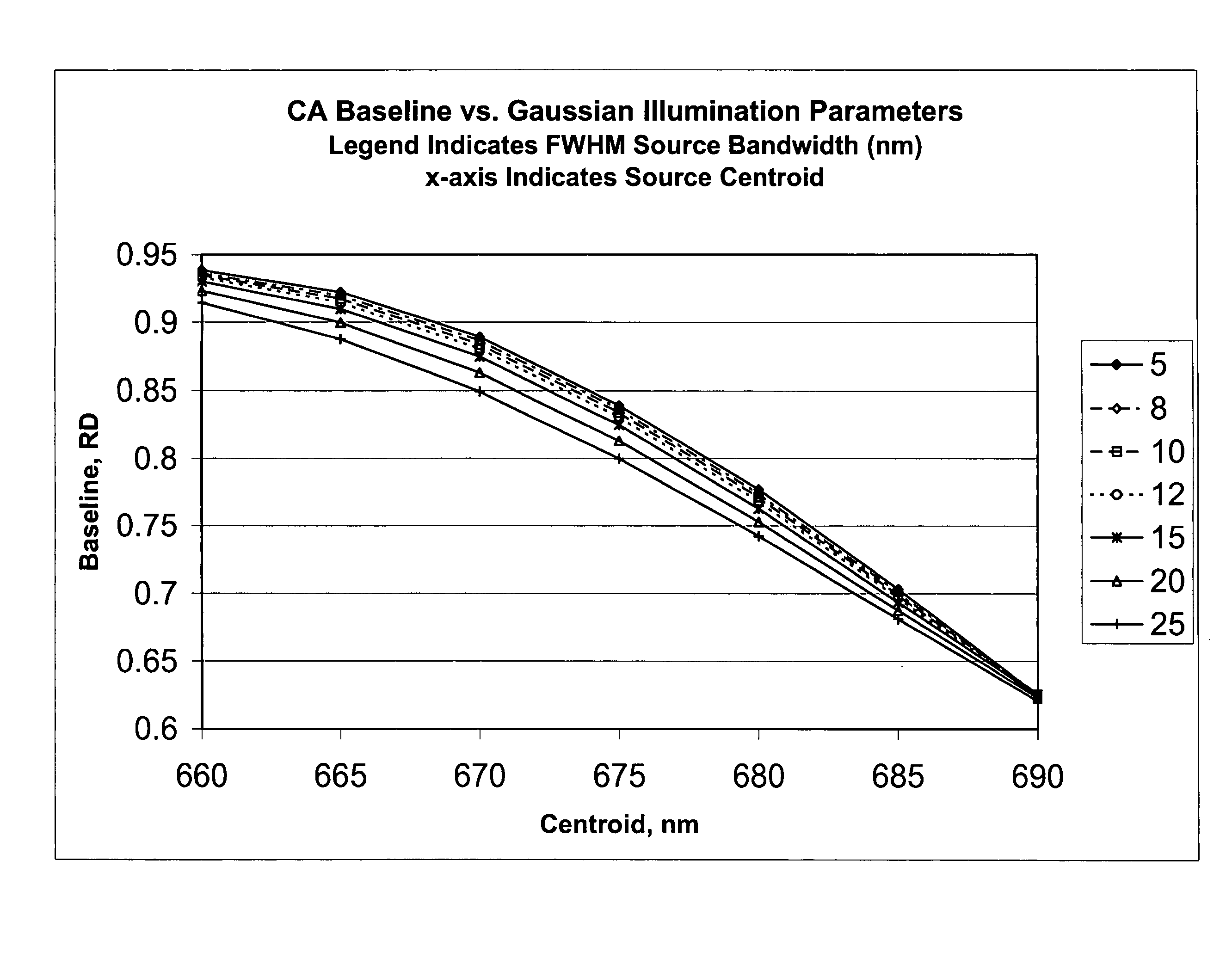
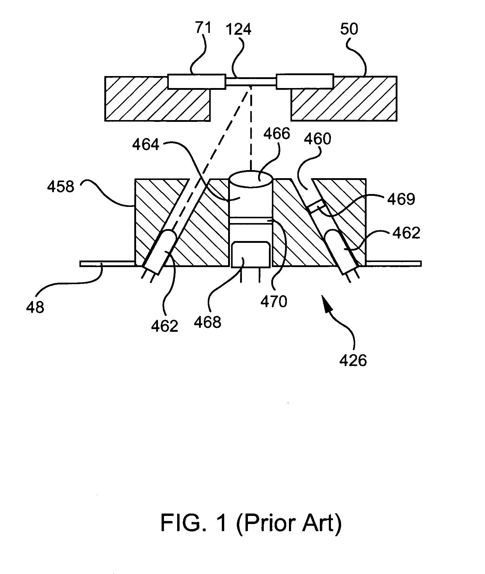
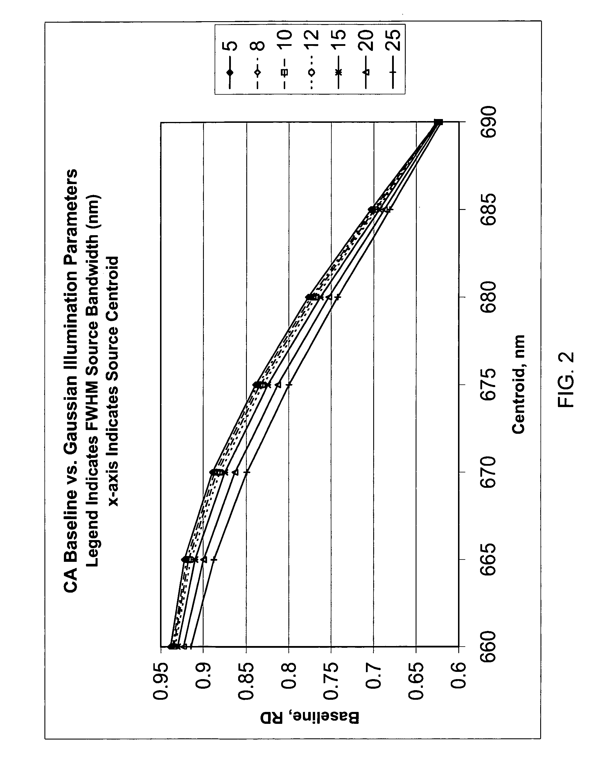
[0039]In accordance with one form of the present invention, a method for calibrating a clinical chemistry instrument may be generally described as measuring the emission spectrum for previously calibrated (that is, intensity-balanced) light emitting diodes (LEDs) used in the optical system of the instrument, measuring the sensitivity spectrum, if such is necessary, of the reflection or transmission sensor (i.e., light detector) used in the optical system of the instrument, and using this information to set one or more corrections having an intercept value (offset), a slope value or higher-order terms, again if such are necessary, to compensate for instrument-to-instrument centroid wavelength and band shape characteristic variability. The emission wavelengths of the LEDs may be measured individually in order to determine if they meet acceptable criteria, or measurements may be taken of two or more LEDs of the same wavelength that are energized to simultaneously emit light. What is me...


PUM

PropertyMeasurementUnit
width at half (bandaaaaaaaaaa
centroid wavelengthaaaaaaaaaa

Abstract

A method of deriving correction for instrument-to-instrument variations in the illumination band centroid wavelengths and wavelength band shapes of the optical systems of clinical chemistry instruments includes the steps of determining the centroid wavelength and wavelength band shape of a light source used in the optical system of a clinical chemistry instrument to provide a determined wavelength band shape and centroid wavelength, comparing the determined wavelength band shape and centroid wavelength with a known reflection density or absorbance wavelength spectrum of a specific type of chemical reagent test to provide a correction value, and calculating the correction value, which is to be used to modify a reflection density or absorbance measurement taken by the instrument of a reagent test of the a specific type of chemical reagent test.

Description

CROSS-REFERENCE TO RELATED APPLICATION[0001]This application is related to U.S. Provisional Application Ser. No. 61 / 211,580, filed on Apr. 1, 2009, and entitled “Method for Calibrating Clinical Chemistry Instruments”, the disclosure of which is incorporated herein by reference. This application claims the benefit of priority under 35 U.S.C. 119 and / or 35 U.S.C. 120 to the aforementioned related provisional application.BACKGROUND OF THE INVENTION[0002]1. Field of the Invention[0003]The present invention generally relates to methods for calibrating clinical chemistry instruments.[0004]2. Description of the Prior Art[0005]Many clinical chemistry instruments measure optical changes caused by addition of a sample to test reagents. For example, some “dry chemistry” instruments measure reflectance factor changes after addition of a sample to a previously dry test slide. As a different example, some “wet chemistry” instruments measure transmittance changes after addition of a sample to a ve...

Claims


Application Information

Patent Timeline
Patent Type & Authority Patents(United States)
IPC IPC(8): G06F19/00G01N21/27
CPCG01N21/274G01N21/55G01N21/59G01N2201/062G01N2201/12746
Inventor MISENER, GARLAND CHRISTIAN
Owner IDEXX LABORATORIES
Learn More