
System and method for metal powder welding

a metal powder welding and system technology, applied in the field of welding, can solve the problems of hammering the free flow of powder from the dispenser to the weld groove, and achieve the effects of high heat input, easy removal, and high heat inpu

Inactive Publication Date: 2015-02-03
ESKANDARI AMIR
View PDF8 Cites 18 Cited by
  • Summary
  • Abstract
  • Description
  • Claims
  • Application Information

AI Technical Summary

Benefits of technology

The patent describes a new method of welding using SAW called HD-SubArc+MP™. This method involves adding metal powder to the welding process using a welding power supply. The use of a constant voltage DC power supply, or a square wave AC power supply, helps to decrease the magnetic effect of the power supply and allows the metal powder to flow more freely without getting stuck. The amount of heat recovered from the metal powder feed rate can be determined using a "Bead on Plate" method with conventional consumables. The method allows for improved utilization of arc energy and results in a more efficient weld.

Problems solved by technology

Decreasing the magnetic effect allows the metal powder to flow more freely without magnetizing the metal powder particles together, thus hampering the free flow of the powder from the dispenser to the weld groove.

Method used


Image

  • System and method for metal powder welding
  • System and method for metal powder welding
  • System and method for metal powder welding

Examples


Embodiment Construction

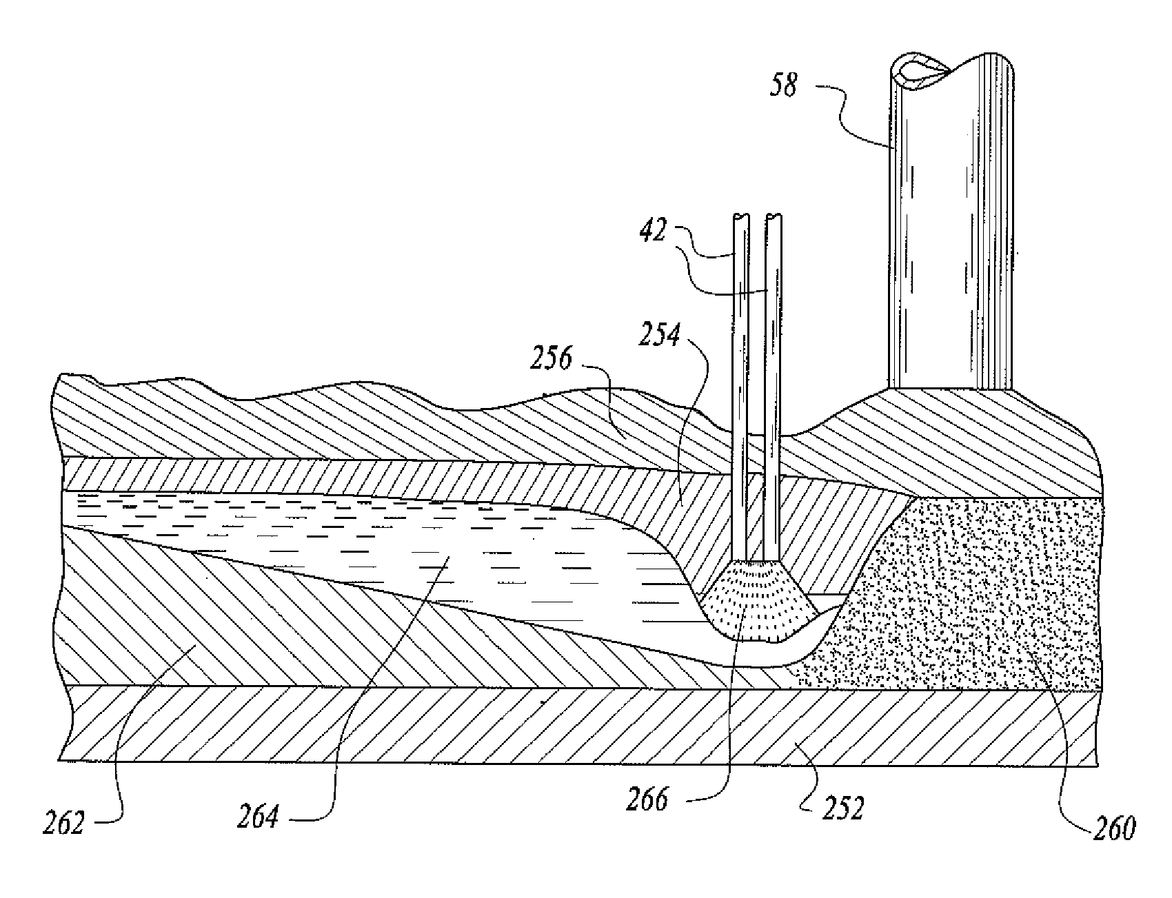
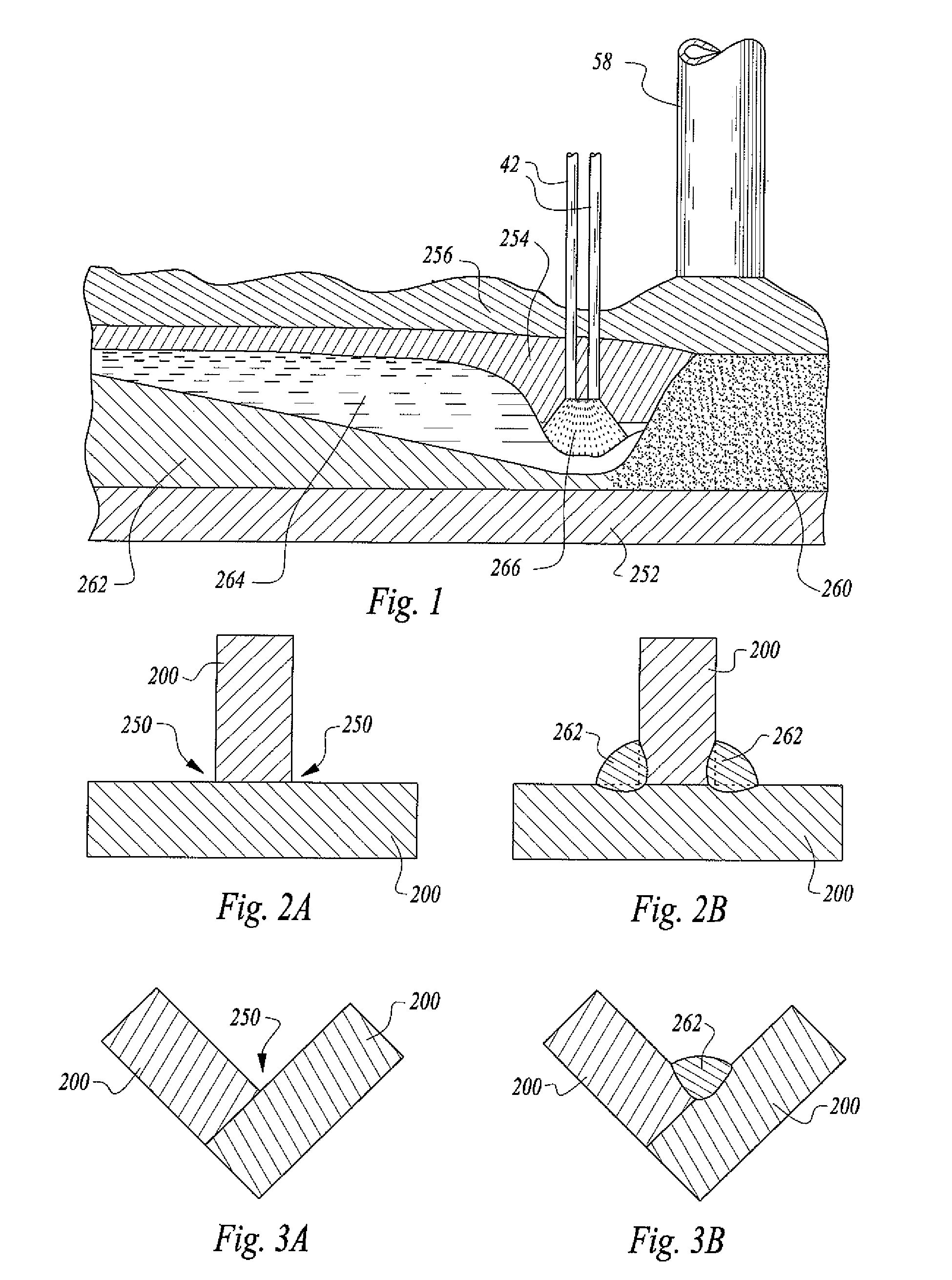
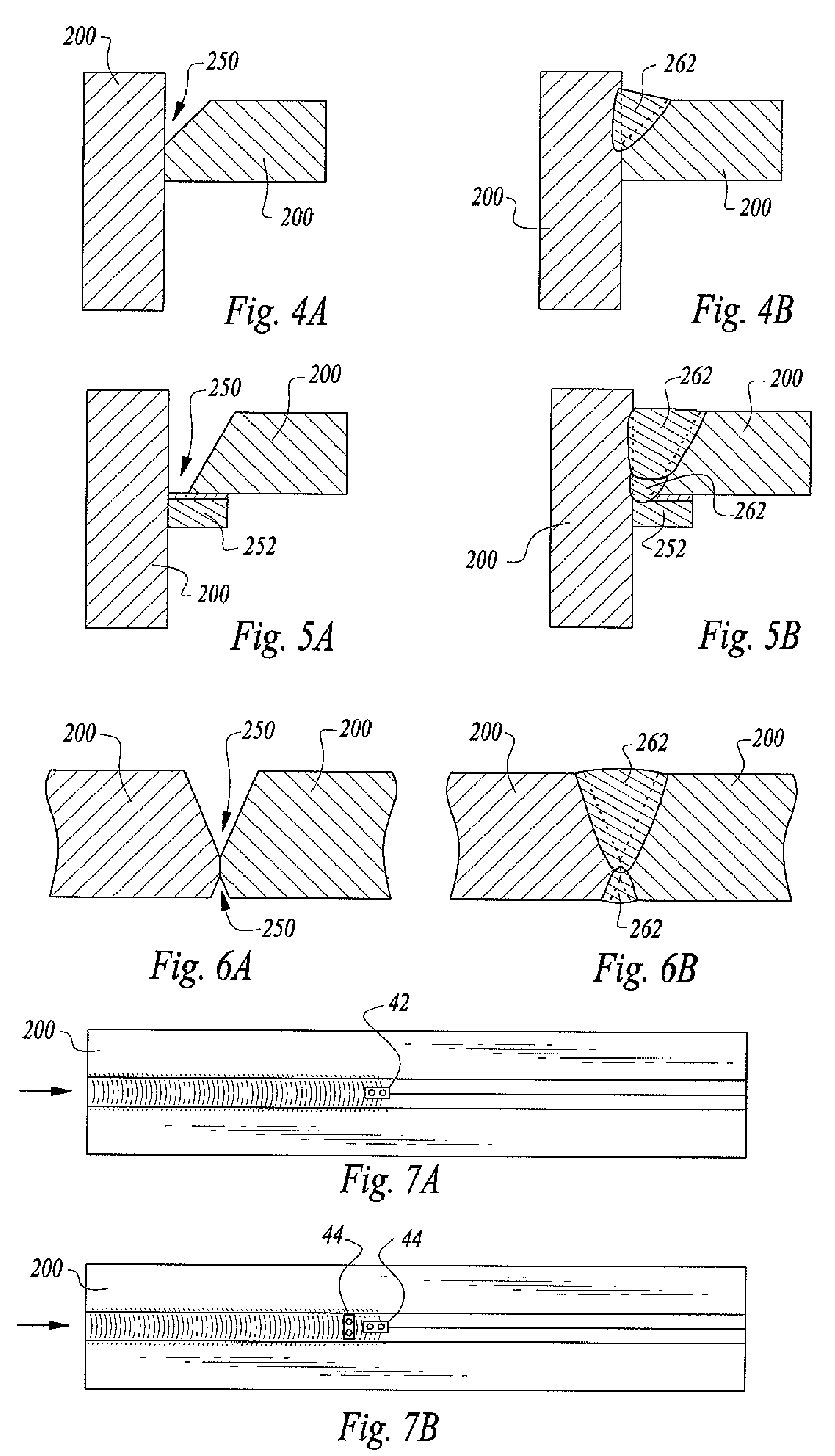
[0094]Referring more specifically to the drawings, for illustrative purposes the system and method for submerged arc metal powder welding applications is embodied generally in FIGS. 1-22. It will be appreciated that the system may vary as to configuration and as to the details of the parts, and that the method of using the system may vary as to details and to the order of steps, without departing from the basic concepts as disclosed herein. The system and method is disclosed generally in terms of HD-SubArc+MP™ welding, and depicted for multiple examples of welding operations as this system and method can be widely used, FIGS. 1-7B. The disclosed apparatus for system and method for metal powder welding applications can be practiced, however, by those having ordinary skill in the art according to the embodiments disclosed herein.

[0095]The motorized light-duty seam-tracker cross-slide assembly and options for the system and method for submerged arc metal powder welding is depicted in F...


PUM

PropertyMeasurementUnit
Percent by massaaaaaaaaaa
Ratioaaaaaaaaaa

Abstract

A system and method for submerged arc metal powder welds includes modular programmable control of: a) a weld torch, and the position of the welding wire(s) from the torch traveling within a weld cavity, b) the rate of metal powder and welding flux added to the weld cavity ahead of the weld torch, c) the matching ratio between of metal powder and welding wire within the weld cavity, and d) a square wave welding torch power supply. An embodiment includes a controlled column and boom manipulator with up to six axes of motion and controlled motorized slide assemblies for single or multi-pass welds. A method of use is also disclosed.

Description

CROSS-REFERENCES TO RELATED APPLICATIONS[0001]None.STATEMENT REGARDING FEDERALLY SPONSORED RESEARCH OR DEVELOPMENT[0002]None.REFERENCE TO A MICRO-FICHE APPENDIX[0003]None.TECHNICAL FIELD[0004]This invention relates to welding. More particularly, the invention is related to a system and method for submerged arc metal powder welding applications including, but not limited to, the Arcmatic™ HD SubArc+MP™ welding system and method.BACKGROUND OF THE INVENTION[0005]For some time now there has been a need for a better method to reduce the cost for making longitudinal welds on beams and columns and for making circumferential and longitudinal welds on heavy wall vessels. A faster method could improve the economics for making long welds on heavy plate. These longitudinal and circumferential welds are generally one of four types: (1) horizontal fillet weld, (2) fully positioned fillet welds, (3) full penetration groove welds, or (4) partial penetration groove welds. These welds have traditiona...

Claims


Application Information

Patent Timeline
IPC IPC(8): B23K9/04
CPCB23K9/18B23K9/186B23K9/188
Inventor BONG, WILLIAM L.
Owner ESKANDARI AMIR
Learn More