
Injecting device and method of filling a holder with separated liquid layers

a technology of injecting device and liquid layer, which is applied in the direction of liquid bottling, liquid dispensing, packaging goods, etc., can solve the problems of inability to achieve optimal separation of liquid layers, drawbacks in the maintenance and vulnerability of the device, and complicated design of the injector, etc., to achieve low flow rate, low outflow rate, and sufficient adhesion

Inactive Publication Date: 2015-01-13
LAYERNATION BEVERAGE SOLUTIONS
View PDF23 Cites 6 Cited by
  • Summary
  • Abstract
  • Description
  • Claims
  • Application Information

AI Technical Summary

Benefits of technology

This invention describes a device that simplifies the process of injecting liquids by using a single feed conduit and reducing the complexity of the device. This makes the device easier to maintain and use with smaller holders. Additionally, the device includes an input unit that allows multiple liquids to be selected, improving the convenience of use. The device operates using a control unit that operates the valves in the channel system. The input unit can be a touchscreen monitor, allowing users to easily select different combinations of liquids. Overall, this invention improves the user experience and simplifies the process of injecting liquids.

Problems solved by technology

A drawback of such a device is the complicated design of the injector through which different conduits with specific outflow openings are provided.
Each conduit has its own pump here, this being a drawback in respect of the maintenance and vulnerability of the device.
Another problem is that the inflow of liquids along the side walls does not slow down the flow sufficiently, whereby an optimal separation of layers is not obtained.
If separating layers are not sufficiently sharp, the obtained layered drink will appear indistinct or untidy, which is undesirable.
With a stepped movement there will be a jerkier movement which may result in disruption of the boundary layers.

Method used


Image

  • Injecting device and method of filling a holder with separated liquid layers
  • Injecting device and method of filling a holder with separated liquid layers
  • Injecting device and method of filling a holder with separated liquid layers

Examples


Embodiment Construction

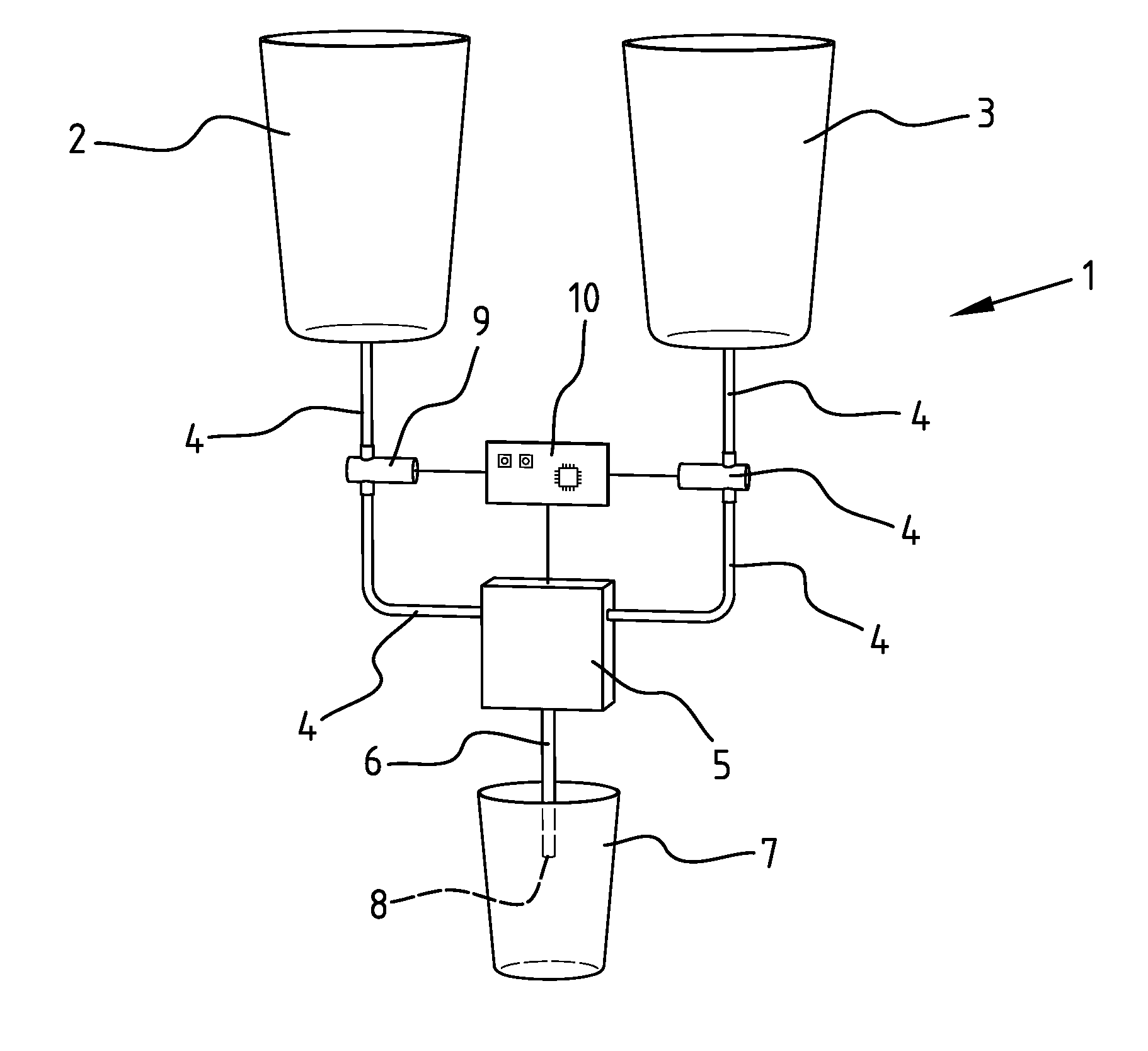
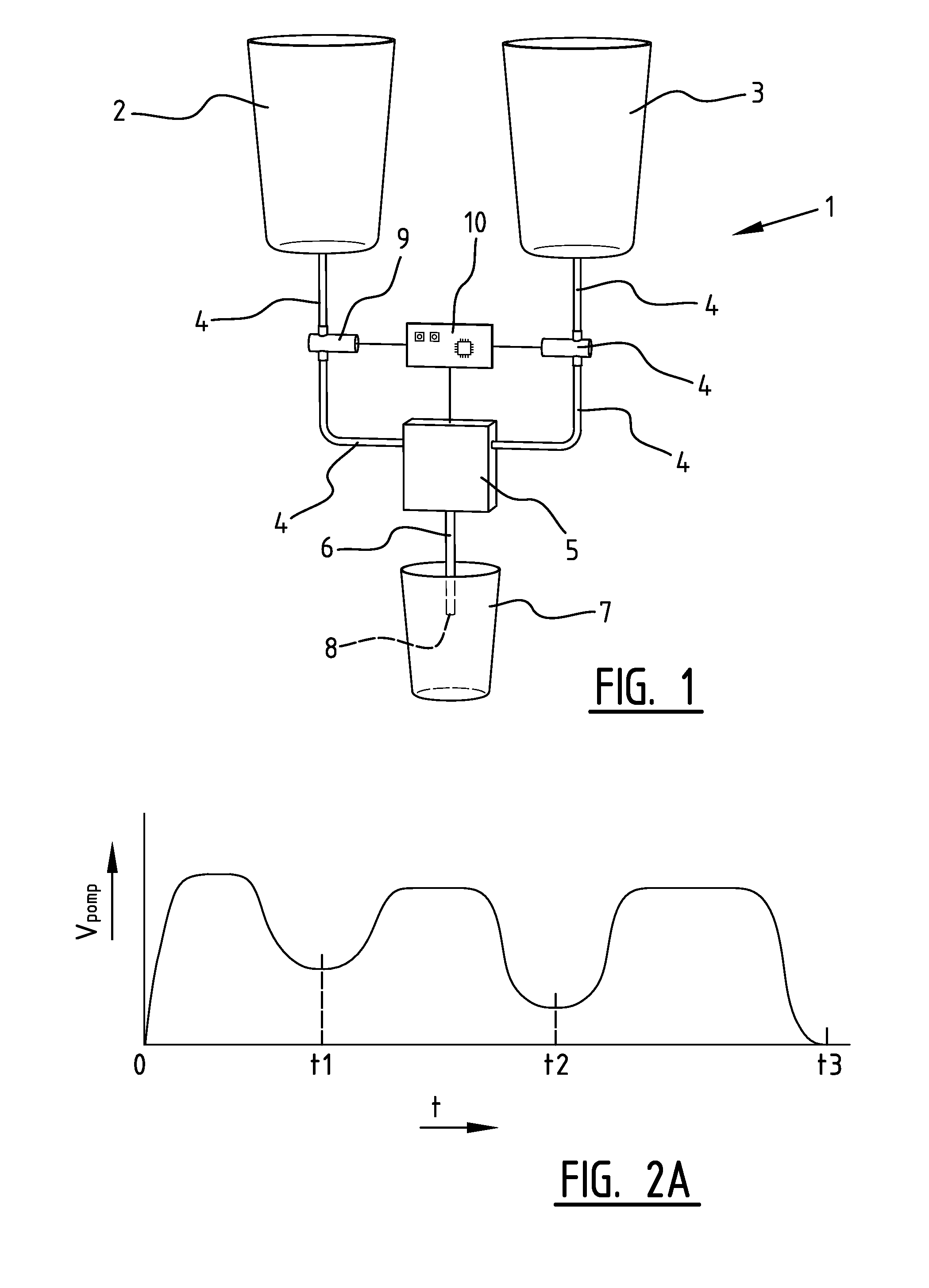
[0034]FIG. 1 shows a schematic view of device 1 according to the invention. The device comprises two liquid containers 2, 3, each comprising a liquid, wherein each of the liquids has a different specific density. The liquid containers are connected via channel system 4 to unit 5, which comprises the pump and the moving means (not further shown). Valves 9 which can selectively close off the feed from a liquid container 2, 3 are arranged in channel system 4. Unit 5 and valves 9 are each operated by control unit 10. A feed conduit 6 with an outflow opening 8 extends from unit 5 which comprises the pump and the moving means (not further shown). A holder 7 is placed under unit 5, wherein feed conduit 6 can be moved up and downward relative to holder 7 by the moving means.

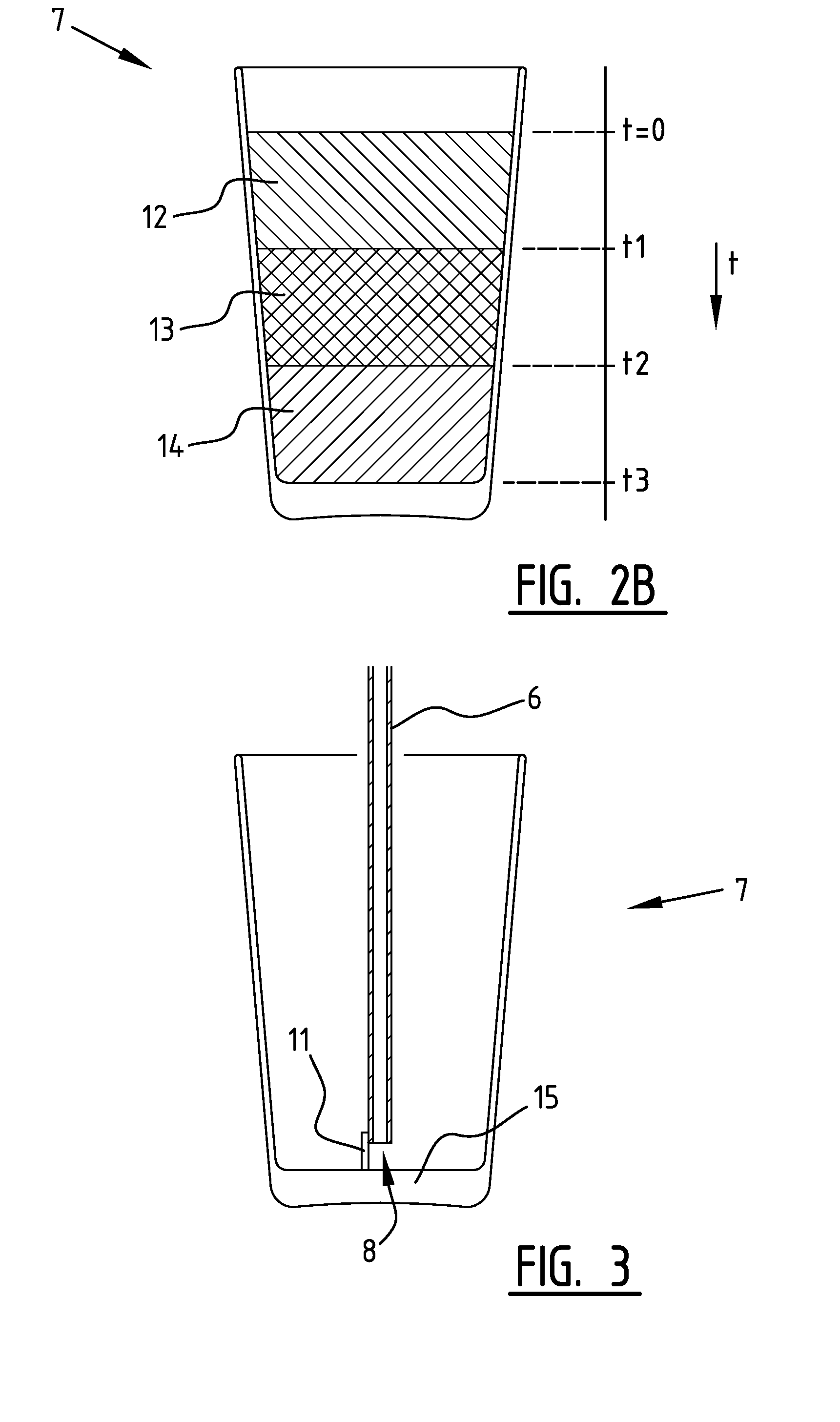
[0035]FIGS. 2A and 2B show the progression of the pump speed over time during filling of holder 7 with successive liquid layers 12, 13, 14, where the density of the successive liquids increases. In these figures holder 7...


PUM

PropertyMeasurementUnit
distanceaaaaaaaaaa
distanceaaaaaaaaaa
distanceaaaaaaaaaa

Abstract

An injecting device for filling a holder with separated liquid layers is provided herein. The device includes at least two containers for holding different liquids, an injector for filling a holder with separated liquid layers and moving means for setting the distance between the holder and the injector. A method for filling a holder with separated liquid layers is also provided. The method includes the steps of placing a holder with bottom, disposing inside the holder, and at a predetermined distance from the bottom of the holder, a feed conduit with an outflow opening for dispensing liquid, and allowing different liquids to flow sequentially out of the feed conduit, wherein the distance between the outflow opening and the bottom is maintained.

Description

INTRODUCTION[0001]The present invention relates to a device comprising:[0002]at least two containers for holding different liquids;[0003]an injector for filling a holder with separated liquid layers which is connected to the containers via a channel system; and[0004]moving means for setting the distance between the holder and the injector.[0005]The present invention also relates to a method for filling a holder with separated liquid layers.BACKGROUND[0006]Such a device and method are known from the publication DE 20 2007 006 521. This publication shows a device for filling a drinking glass with separated liquid layers. The device comprises one injector which is connected via three channels to three liquid reservoirs. The injector is provided with three separated feed conduits, each with its own outflow opening. Each individual feed conduit is connected to only one liquid reservoir. The orientation of the outflow opening for the liquid which flows first into the drinking glass is dir...

Claims


Application Information

Patent Timeline
Patent Type & Authority Patents(United States)
IPC IPC(8): B67D1/08A47J31/00B67D1/00
CPCA47J31/002B67D1/0041B67D1/0888B67D1/0894
Inventor KINDS, DIEDERIK JASPERPOPPENK, FEDDE MARTIJNVAN MEER, PHILIP MARKUS
Owner LAYERNATION BEVERAGE SOLUTIONS
Learn More