
Overmolded vehicle license plate frame and bumper assembly

a license plate frame and bumper technology, applied in the field of overmolded vehicle license plate frame and bumper assembly, can solve the problems of damage, dimples, cracks or scratches, and bumpers on vehicles, and achieve the effects of higher elasticity and deformation, and higher tensile strength

Active Publication Date: 2015-01-13
MACNEIL IP
View PDF37 Cites 4 Cited by
  • Summary
  • Abstract
  • Description
  • Claims
  • Application Information

AI Technical Summary

Benefits of technology

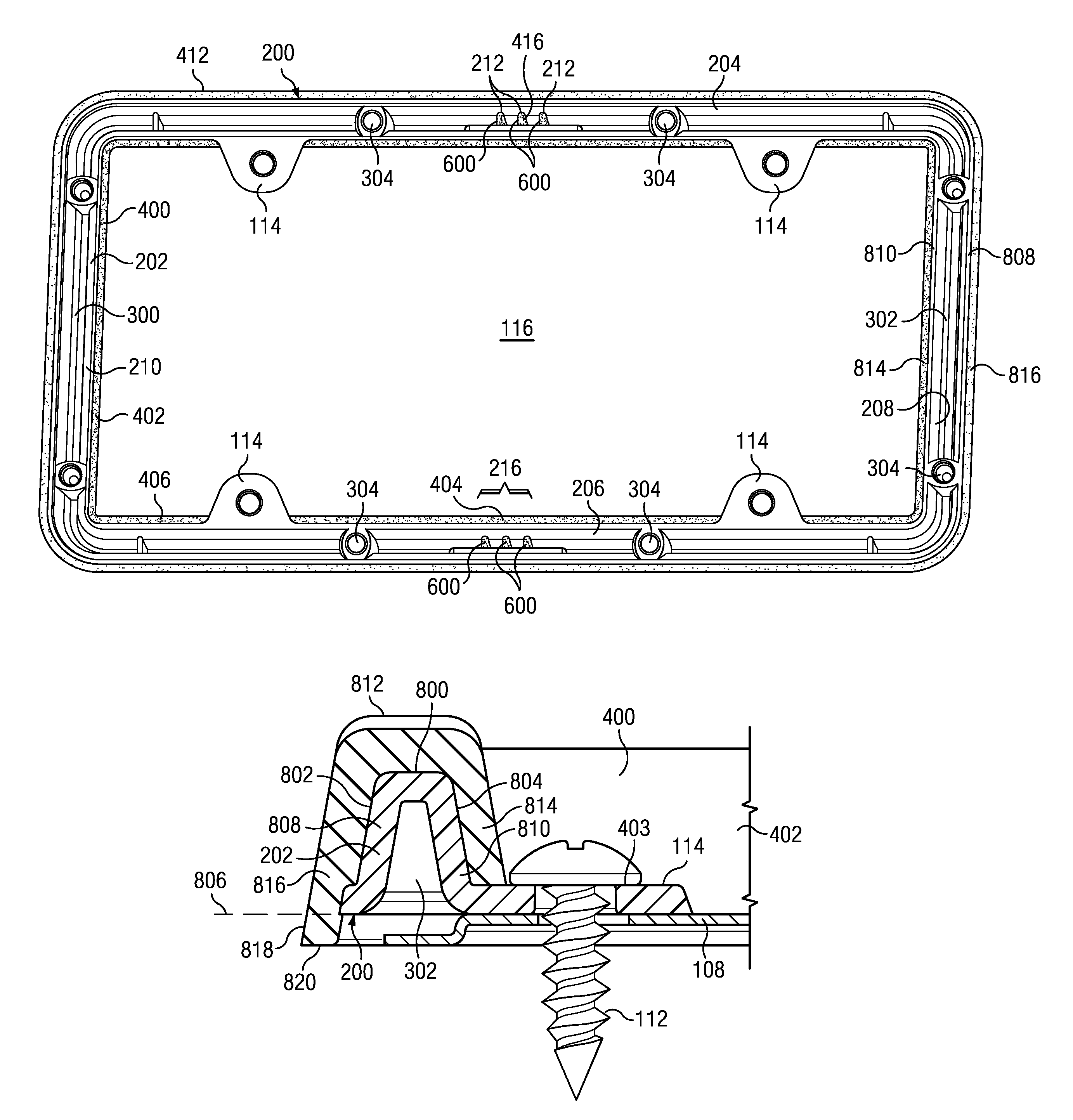
[0009]One technical advantage of the invention is that the employed polymer compounds can be selected to have different properties. For example, the first polymer compound can be selected for toughness and tensile strength. The second polymer compound can be selected for impact resistance and elasticity. Intentionally omitting the overmold component from the screw head-receiving areas of the mounting screw tabs assures that only the relatively tough and deformation-resistant first polymer compound will receive any compression force exerted by the mounting screw heads, and that the higher tensile strength of the first polymer compound will better resist any force tending to tear the assembly off of the vehicle. The substrate further forms a multiple-face frame on which can be cohesively overmolded the bumper element, which can exhibit a higher elasticity and deformation than the first polymer compound, so as to better protect the vehicle upon which the device is mounted, the impacting vehicle, and the license plate. Formation of the substrate frame element as a channel permits the molding of the substrate to a substantially uniform nominal wall thickness, and further admits of the inclusion of one or more gas vents to remove gas in the overmolding step that would otherwise mar the finished product.
is that the employed polymer compounds can be selected to have different properties. For example, the first polymer compound can be selected for toughness and tensile strength. The second polymer compound can be selected for impact resistance and elasticity. Intentionally omitting the overmold component from the screw head-receiving areas of the mounting screw tabs assures that only the relatively tough and deformation-resistant first polymer compound will receive any compression force exerted by the mounting screw heads, and that the higher tensile strength of the first polymer compound will better resist any force tending to tear the assembly off of the vehicle. The substrate further forms a multiple-face frame on which can be cohesively overmolded the bumper element, which can exhibit a higher elasticity and deformation than the first polymer compound, so as to better protect the vehicle upon which the device is mounted, the impacting vehicle, and the license plate. Formation of the substrate frame element as a channel permits the molding of the substrate to a substantially uniform nominal wall thickness, and further admits of the inclusion of one or more gas vents to remove gas in the overmolding step that would otherwise mar the finished product.

Problems solved by technology

More recently, the bumpers on vehicles, such as automobiles, sport utility vehicles, vans, minivans and light trucks, have become more notional and more susceptible to damage from even slight impacts.
A relatively low-velocity impact sustained by a conventional “bumper” may cause damage such as dimples, cracks or scratching that can only be remedied by an expensive visit to an auto body shop.
In many instances, this damage is caused by the license plate, license plate frame and / or license plate mounting screws carried by the bumper of the impacting vehicle.
These prior art attempts may suffer from problems such as delamination and tearing or other physical failure, as it is difficult to find a single material that combines sufficient structural strength and sufficient elasticity when subjected to an impact.

Method used


Image

  • Overmolded vehicle license plate frame and bumper assembly
  • Overmolded vehicle license plate frame and bumper assembly
  • Overmolded vehicle license plate frame and bumper assembly

Examples


Embodiment Construction

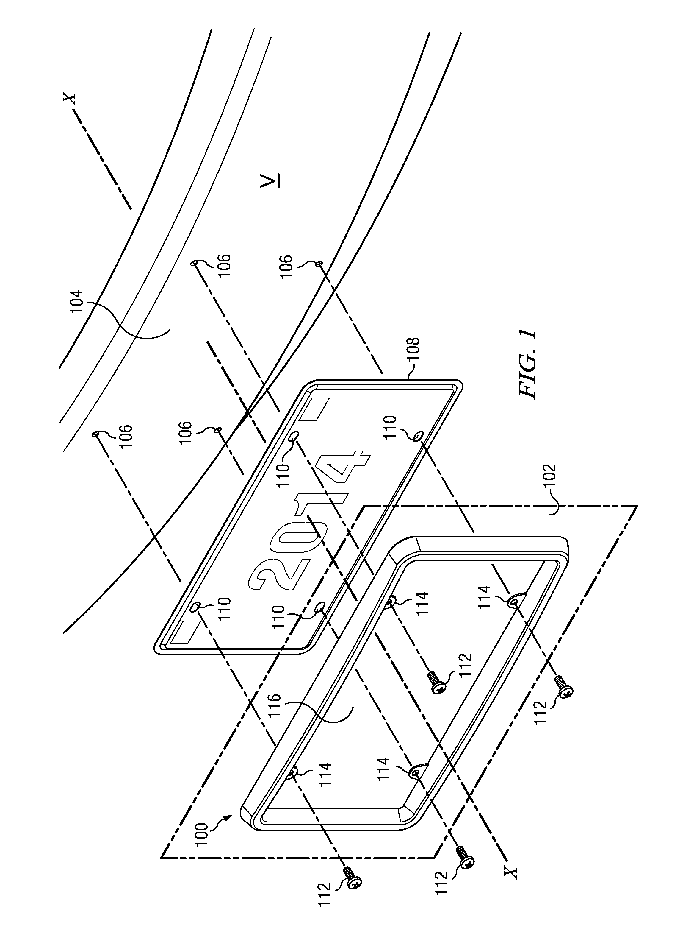
[0018]As shown in FIG. 1, a license plate frame and bumper assembly 100 according to the invention is, in use, centered on an axis X. The assembly 100 generally resides in a substantially vertical plane 102 that is orthogonal to the axis X. While axis X typically is parallel to an axis of travel of a vehicle V to which assembly 100 is to be attached, and furthermore typically is in the centered on vehicle V, axis X might in some instances be canted to the horizontal, and some vehicle manufacturers choose to affix the license plate to vehicle V at an off-center location.

[0019]The vehicle V typically has a bumper 104 (here, a front bumper is shown) that provides screw-threaded license plate mounting holes 106. The mounting holes 106 may drilled directly into the bumper 104, as shown, or the manufacturer may instead provide a more elaborate niche, receptacle or mounting plate for the license plate 108, and in this last instance (not shown) the mounting holes 106 will be a portion of th...


PUM


Abstract

A vehicle license plate frame and bumper assembly has a substrate formed of a high-durometer first polymer compound, and an overmold component formed of a lower-durometer, second polymer compound that is chemically compatible with the first polymer compound. The substrate includes an endless frame with forward, inner and outer faces, and license plate screw mounting tabs inwardly extending from the frame. The overmold component includes a bumper cohesively bonded to the frame but not to screw head-receiving areas of the tabs.

Description

BACKGROUND OF THE INVENTION[0001]Vehicle license plate frames and holders have existed in the automotive aftermarket for about as long as there have been vehicle license plates. More recently, the bumpers on vehicles, such as automobiles, sport utility vehicles, vans, minivans and light trucks, have become more notional and more susceptible to damage from even slight impacts. Vehicle bumpers used to be prominent structures fashioned of chrome-plated steel and offered some modicum of protection from low-velocity impacts, but now more typically are integrated with the vehicle body, are made of flexible plastic and are painted. A relatively low-velocity impact sustained by a conventional “bumper” may cause damage such as dimples, cracks or scratching that can only be remedied by an expensive visit to an auto body shop. In many instances, this damage is caused by the license plate, license plate frame and / or license plate mounting screws carried by the bumper of the impacting vehicle.[0...

Claims


Application Information

Patent Timeline
Patent Type & Authority Patents(United States)
IPC IPC(8): G09F7/00B60R13/10
CPCB60R13/105
Inventor MASANEK, JR., FREDERICK W.MACNEIL, DAVID F.
Owner MACNEIL IP
Learn More