Low-profile broadband multiple antenna

a broadband multiple antenna and low-profile technology, applied in the field of multiple antennas, can solve problems such as increasing antenna siz

Inactive Publication Date: 2014-12-30
THALES SA
View PDF12 Cites 3 Cited by
  • Summary
  • Abstract
  • Description
  • Claims
  • Application Information

AI Technical Summary

Benefits of technology

[0010]One of the objectives of the invention is to provide an antenna system which is capable of covering a wide frequency band based on thin, and therefore low-profile, radiating elements. To achieve thes...

Problems solved by technology

The drawbacks with this type of structure notably stem from the use of the stub.
Such a system, while effective, does, however, present the drawback of requiring the implementation, in order to cover a wide frequency band, thick ra...

Method used


Image

  • Low-profile broadband multiple antenna
  • Low-profile broadband multiple antenna
  • Low-profile broadband multiple antenna

Examples


Embodiment Construction

[0030]In order to better understand the object of the present invention, the description will be given as a nonlimiting example in the context of a low-profile double antenna used for radio communication equipment, in particular in the 225-400 MHz UHF (ultra-high frequency) band, intended for installation and use on stationary or moving vehicles. The antenna can thus be used in a space diversity context, that is to say that each antenna element operates in the same frequency range. The antenna may operate in transmitting mode, in receiving mode or even in transmitting / receiving mode.

[0031]More generally, the antenna structure may also consist of a number of dipoles n with n greater than or equal to 2. Each dipole can be adapted to operate in one and the same frequency range, or even in different frequency ranges.

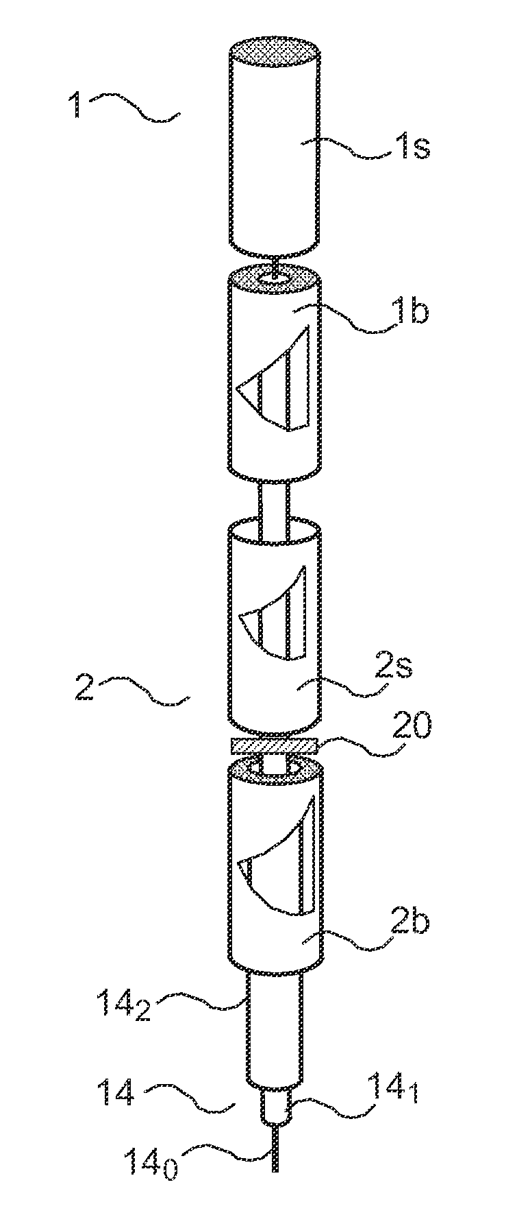
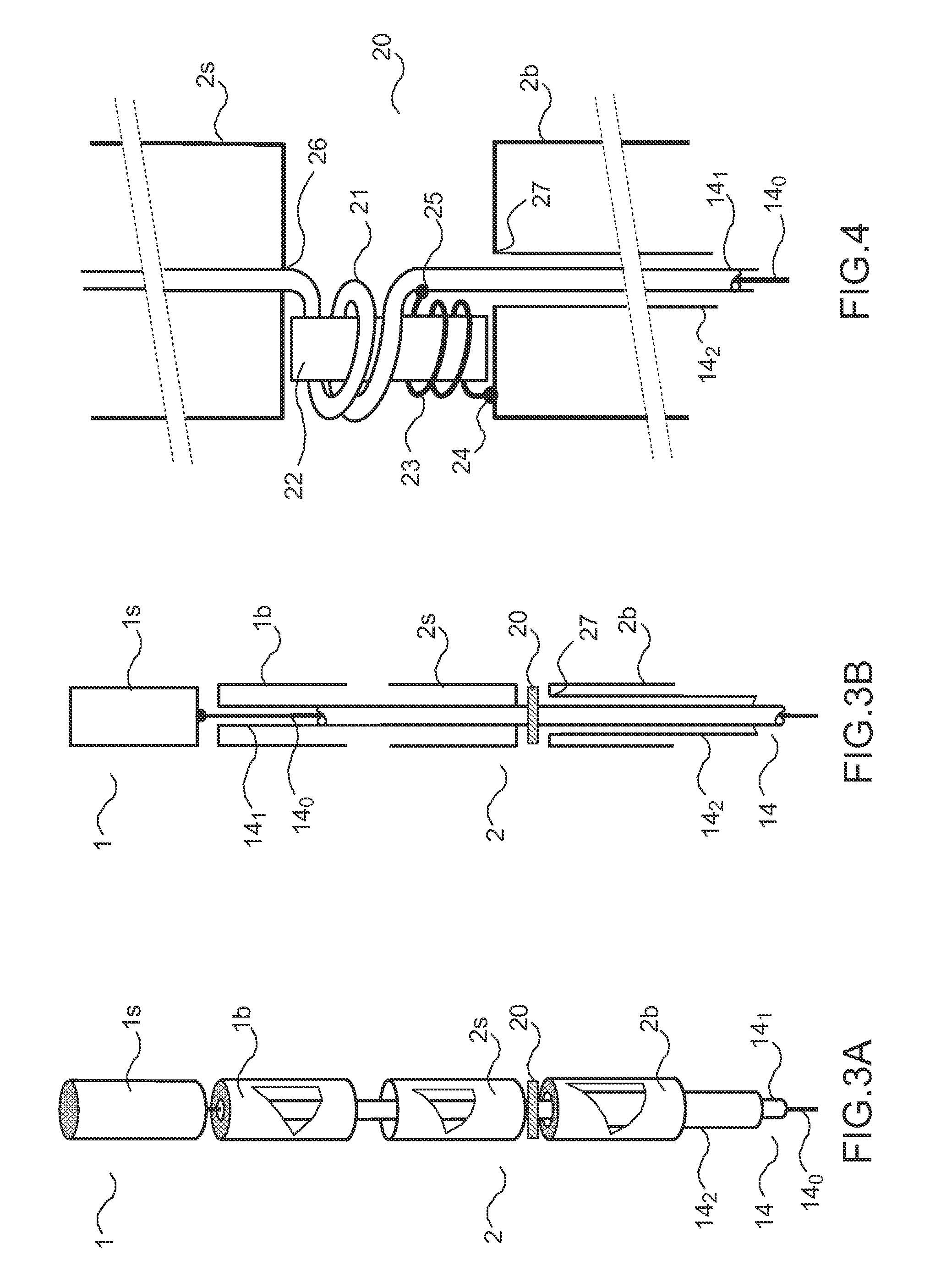
[0032]FIGS. 3A and 3B (respectively seen in perspective and seen in cross section) represent an exemplary embodiment of a double antenna according to the invention.

[0033]The...


PUM


Abstract

A low-profile broadband multiple antenna, comprises: a dipole arranged in the top part of said antenna, said dipole comprising at least one first top antenna element connected to the core of a multi-axial cable comprising a core and n sheaths and the bottom individual element of which is connected to the first sheath adjacent to the core, a connection device positioned between a top element of a dipole and the bottom element of said dipole the top element is connected to the sheath of index (k−1) of the multi-axial cable after the assembly comprising the core and the sheaths of index (1 to k−1) has been wound in Q turns around a magnetic core and the bottom element of the dipole is connected to the sheath of index k, and said connection device comprises at least one single-wire winding of P turns on the same magnetic core linking said bottom element of said dipole to the sheath of index (k−1), at the point corresponding to the start of the winding in order to provide the broadband impedance matching and the power supply for the dipole.

Description

CROSS-REFERENCE TO RELATED APPLICATIONS[0001]This application is a National Stage of International patent application PCT / EP2010 / 052303, filed on Feb. 23, 2010, which claims priority to foreign French patent application No. FR 0902008, filed on Apr. 24, 2009, the disclosures of which are incorporated by reference in their entirety.FIELD OF THE INVENTION[0002]The subject of the invention relates to the multiple antennas that are used notably for radio communication equipment.BACKGROUND[0003]The antennas according to the invention are applied, for example, to equip vehicles and for a frequency band varying from 225 to 400 MHz. They may operate with space diversity, all the antenna elements forming the antenna then operating in one and the same frequency range. The antennas may also consist of several antenna elements operating in mutually different frequency bands. The position of the different antenna elements forming the antenna, relative to one another, depends on the application.[...

Claims


Application Information

Patent Timeline
IPC IPC(8): H01Q21/10H01Q1/00H01Q9/04H01Q9/28H01Q1/52H01Q5/00H01Q9/16H01Q5/15H01Q5/321H01Q5/40
CPCH01Q21/10H01Q9/28H01Q1/52H01Q5/0034H01Q5/00H01Q5/0072H01Q5/40H01Q5/321
Inventor NGO, BUI, HUNG, FREDERIC
Owner THALES SA
Why Eureka
Try Eureka