Eureka AIR delivers breakthrough ideas for toughest innovation challenges, trusted by R&D personnel around the world.

Slide switch

a sliding switch and slider technology, applied in the direction of contact mechanisms, buckles, transportation and packaging, etc., can solve the problems of slider biting a foreign substance, affecting both fixed contact points and moving contact points, contaminated contact points, etc., to reduce the entry reduce the biting of a foreign substance

Inactive Publication Date: 2014-12-30
HOSIDEN CORP
View PDF5 Cites 4 Cited by
  • Summary
  • Abstract
  • Description
  • Claims
  • Application Information

AI Technical Summary

Benefits of technology

[0006]It is an object of the present invention to provide a slide switch that can reduce entrance and biting of a foreign substance and is excellent in reliability.
[0008]According to the present invention, such effects are exhibited that it is possible to reduce entrance of a foreign substance by the side wall formed in the slider, and it is possible to reduce biting of a foreign substance by equipping the foreign substance elimination groove.

Problems solved by technology

Since the moving contact points are exposed from the gap, there is a possibility that a foreign substance enters from the gap before and upon incorporating the slide switch 9 into the buckle device and further during the use of the buckle device, and any or both of the fixed contact points and the moving contact points are contaminated and affected by the foreign substance.
However, as the gap is made smaller, there is an increasing possibility that the slider bites a foreign substance adhered to a facing surface of the body during slide.
Due to the biting of a foreign substance, an action failure occurs, such as (1) sliding movement is not allowed to a fundamentally required stroke (full stroke), (2) the slider is not allowed to slidingly move, and (3) the load to slidingly move the slider increases.

Method used


Image

  • Slide switch
  • Slide switch
  • Slide switch

Examples


first embodiment

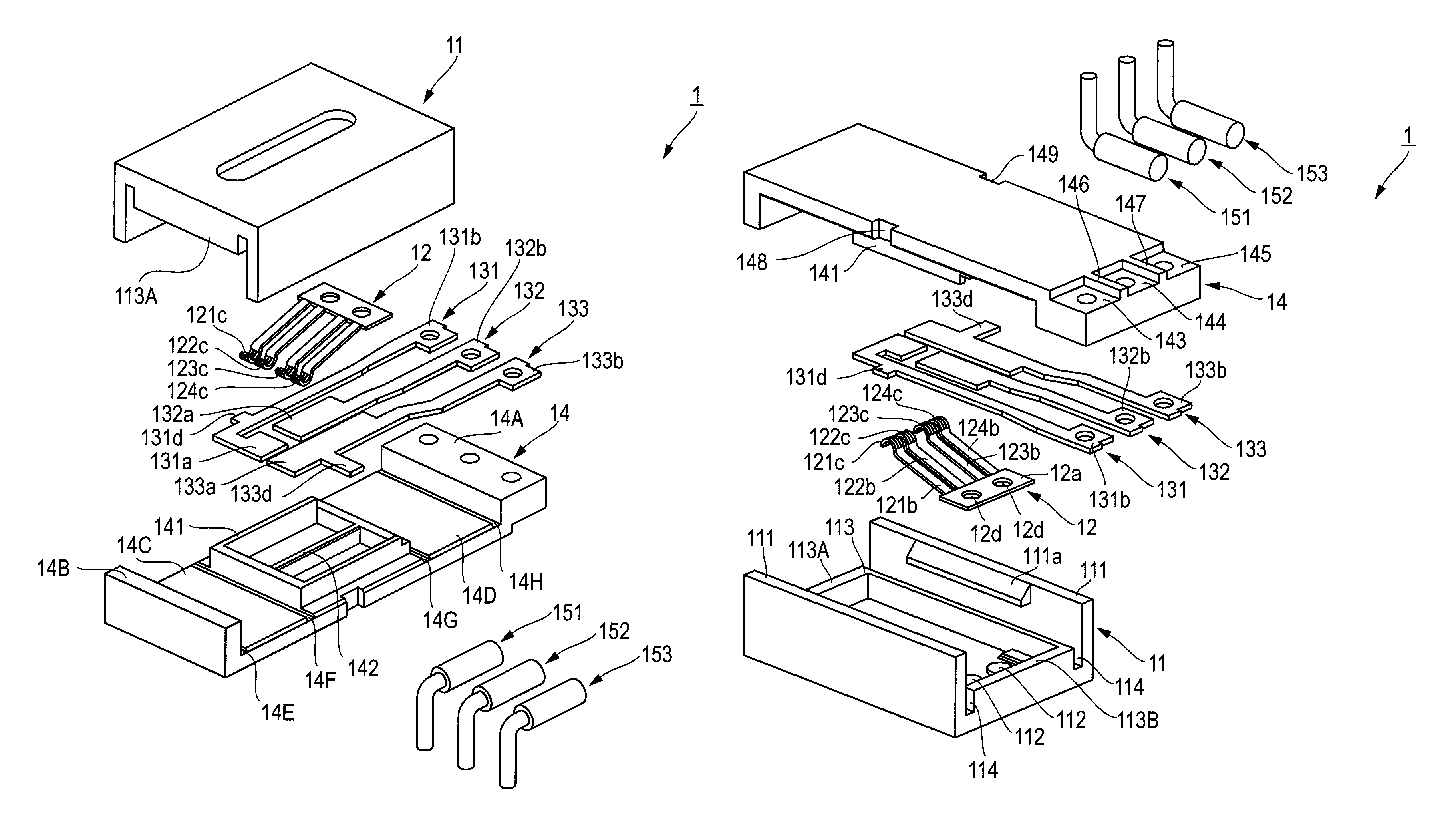
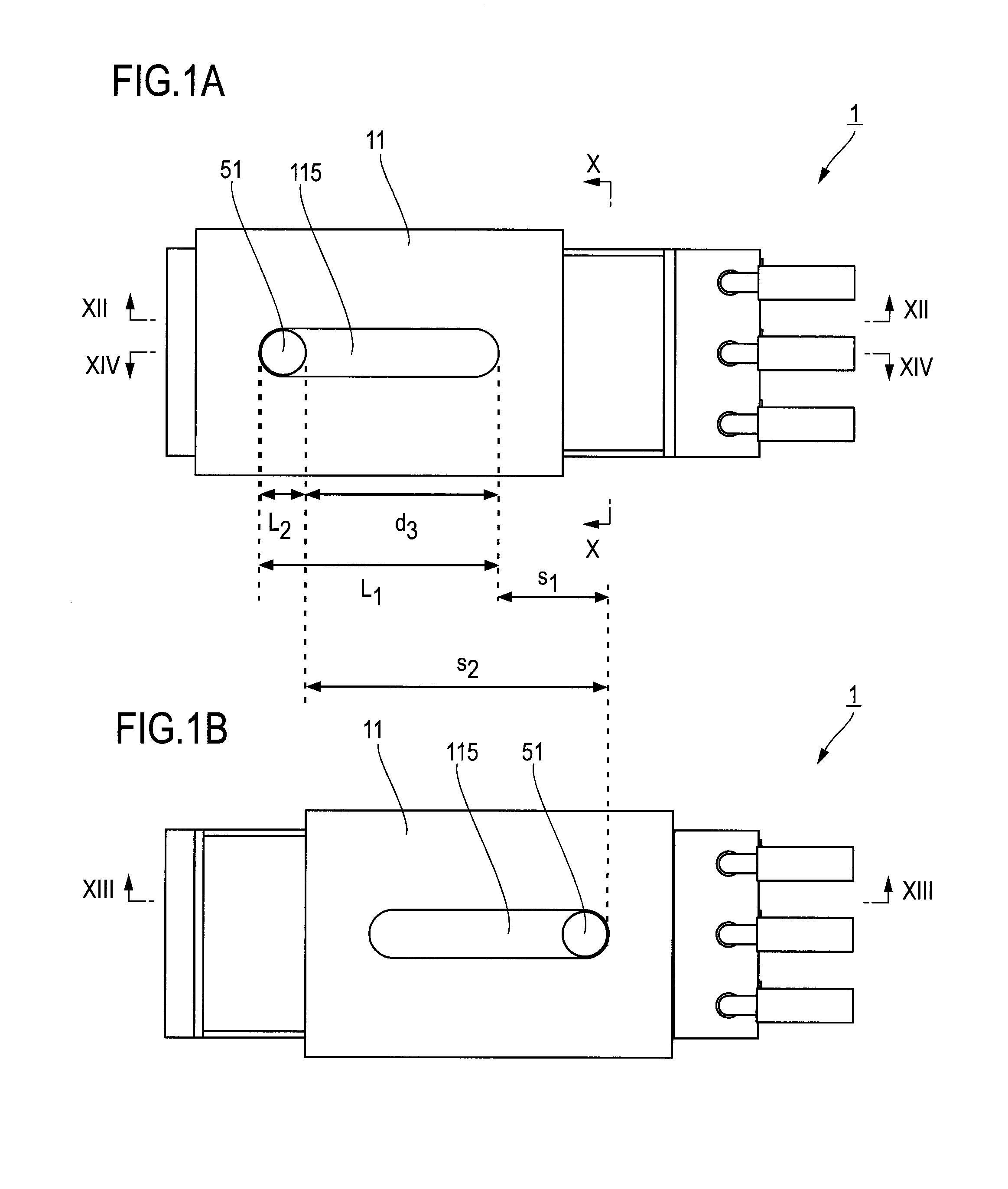
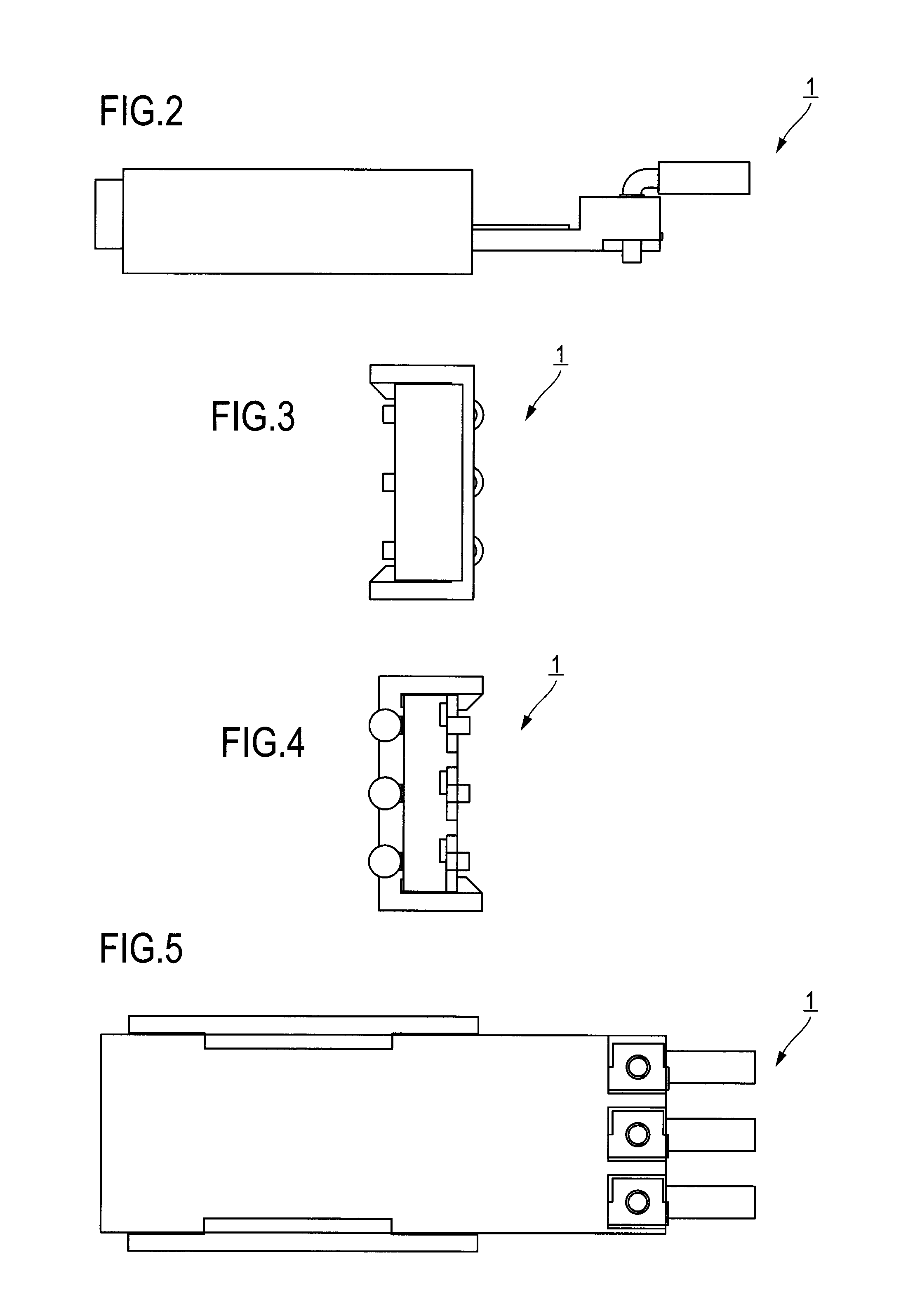
[0030]FIG. 1A illustrates a front view of a slide switch 1 according to a first embodiment in a case that a slider 11 is located in an initial position, and FIG. 1B illustrates a front view in a case that the slider 11 is located in a post-action position. FIG. 2 illustrates a bottom view of the slide switch 1 according to the first embodiment, FIG. 3 illustrates a left side view thereof, FIG. 4 illustrates a right side view thereof, and FIG. 5 illustrates a back view thereof. FIG. 6 illustrates a perspective view of the slide switch 1 viewed from the front, FIG. 7 illustrates an exploded perspective view thereof, FIG. 8 illustrates a perspective view of the slide switch 1 viewed from the back, and FIG. 9 illustrates an exploded perspective view thereof. In some of the drawings, three harnesses 151 through 153 are collectively illustrated, and in FIGS. 1A, 1B, and 6, the moving part 51 is illustrated collectively.

[0031]The slide switch 1 includes the slider 11, an armature 12, three...


PUM


Abstract

A slider is slidably held in a body and is pushed by insertion of an object to slidingly move. Terminals are provided with fixed contact points disposed on a surface, facing the slider, of the body along a sliding movement direction. The armature is attached to the slider and is provided with moving contact points that slide on a fixed contact point disposition surface of the body in association with sliding movement of the slider. The slider has an armature mounting surface with a side wall protrudingly formed in one end in the sliding movement direction. The body has a facing surface facing an end surface of the side wall in an entire range of sliding movement. At least any one of an end in the sliding movement direction of the end surface of the side wall and an end in the sliding movement direction of the facing surfaces of the body has a foreign substance elimination groove formed therein.

Description

TECHNICAL FIELD[0001]The present invention relates to a slide switch that senses an extracted state and an inserted and engaged state of an object.BACKGROUND ART[0002]Japanese Patent Application Laid Open No. 2011-62423 (hereinafter, referred to as Patent Literature 1) is understood as a conventional technique of a slide switch. FIG. 16 is an exploded perspective view illustrating a configuration of a slide switch 9 according to Patent Literature 1. The slide switch 9 is provided with a body 920, a slider 930 that is held slidingly movably in the body 920 and is pushed by a moving part on a buckle device side to slidingly move, fixed contact points 941 through 943 that are disposed on a surface, facing the slider 930, of the body 920 along a sliding movement direction, and a movable armature 944 that is attached to the slider 930 and slides on a fixed contact point disposition surface of the body 920 in association with sliding movement of the slider 930. The body 920 has a tip end ...

Claims


Application Information

Patent Timeline
Patent Type & Authority Patents(United States)
IPC IPC(8): H01H15/04H01H1/36H01H15/14H01H9/04B60R22/48H01H3/16
CPCB60R22/48H01H9/04H01H1/365H01H15/14H01H15/04B60R2022/4816A44B11/25H01H15/02
Inventor YAMANAKA, SATOSHIDESAKI, KENJIROKOIZUMI, HIROFUMI
Owner HOSIDEN CORP
Why Eureka
Eureka Blog
Learn More