Ergonomic and semi-automatic manipulator, and applications to instruments for minimally invasive surgery

a semi-automatic and manipulator technology, applied in the direction of arms, joints, diagnostics, etc., can solve the problem of bulky transmission of the different movements of the tool carrier, and achieve the effect of reducing bulk and ensuring the rigidity of transmission

Active Publication Date: 2014-12-30
DEXTERITE SURGICAL
View PDF11 Cites 1023 Cited by
  • Summary
  • Abstract
  • Description
  • Claims
  • Application Information

AI Technical Summary

Benefits of technology

[0021]It has, however, been shown that with such a device the transmission of the different movements of the tool carrier is bulky, in particular by the arrangement of a plurality of joints in cascade along the longitudinal axis, and also because no means is provided to carry out all the transmissions of movement within a small diameter of the distal part of the manipulator. Thus a need exists to design further transmission means, simultaneously providing reduced bulk and sufficient rigidity of the transmissions which require it.

Problems solved by technology

It has, however, been shown that with such a device the transmission of the different movements of the tool carrier is bulky, in particular by the arrangement of a plurality of joints in cascade along the longitudinal axis, and also because no means is provided to carry out all the transmissions of movement within a small diameter of the distal part of the manipulator.

Method used


Image

  • Ergonomic and semi-automatic manipulator, and applications to instruments for minimally invasive surgery
  • Ergonomic and semi-automatic manipulator, and applications to instruments for minimally invasive surgery
  • Ergonomic and semi-automatic manipulator, and applications to instruments for minimally invasive surgery

Examples


Embodiment Construction

[0069]Firstly, the overall structure of a manipulator according to the invention is considered, as illustrated in FIGS. 1 to 12.

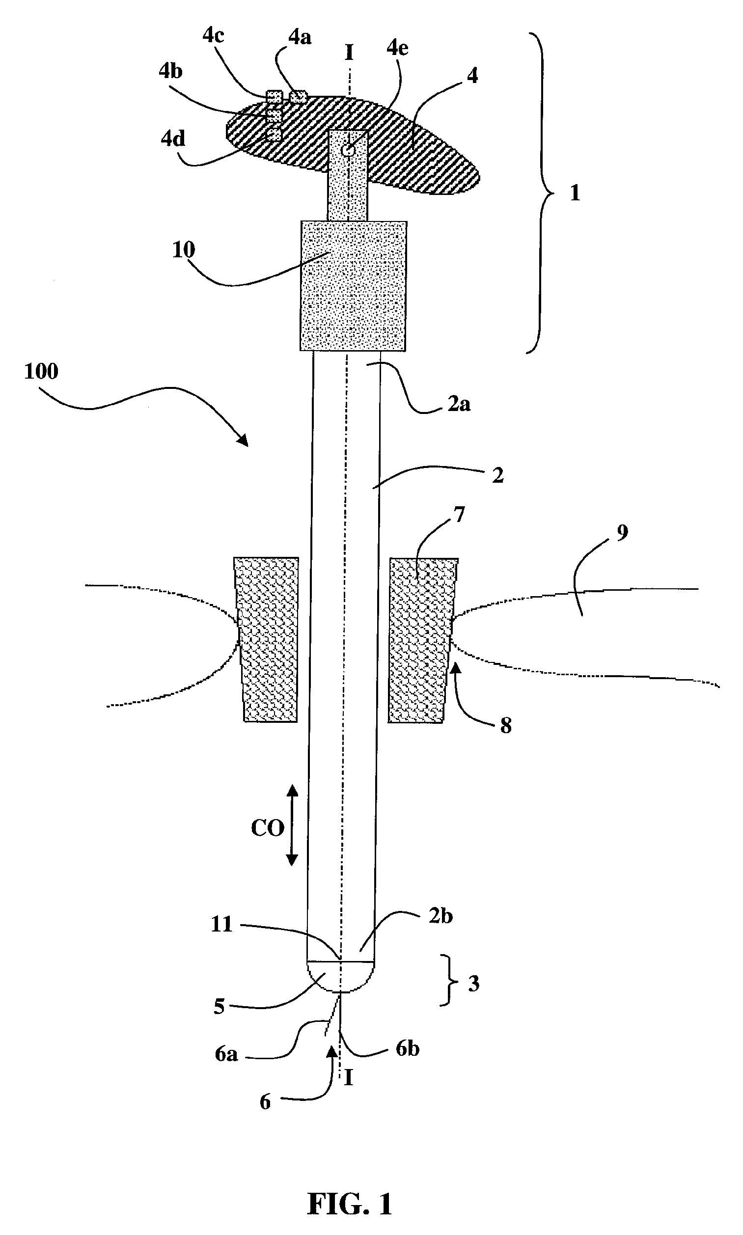
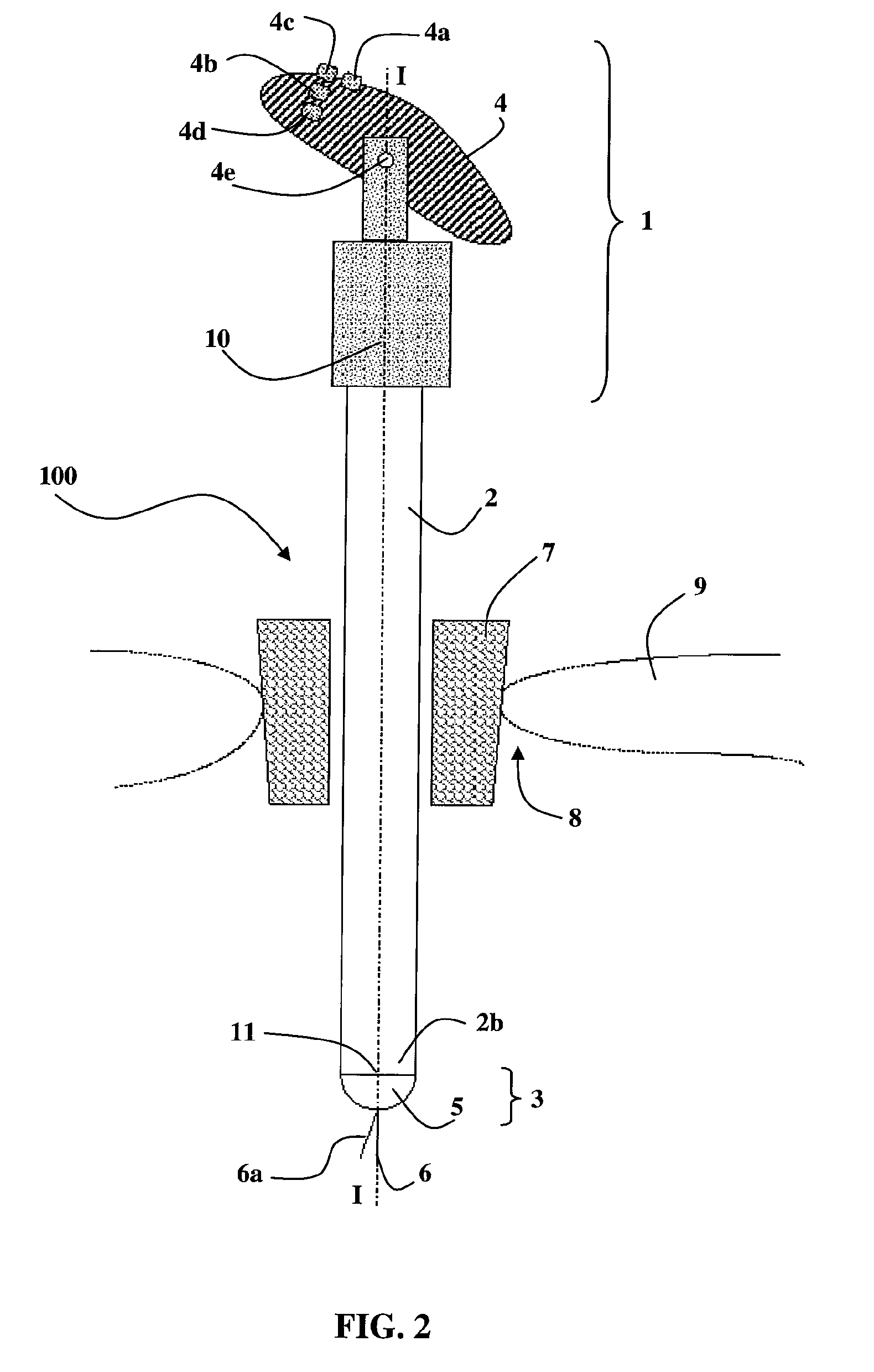
[0070]Such a manipulator 100 generally comprises a control unit 1, a connecting arm 2 and a working unit 3.

[0071]The control unit 1 is mounted on the proximal end 2a of the connecting arm 2 whilst the working unit 3 is mounted on the distal end 2b of the connecting arm 2.

[0072]The control unit 1 comprises a handle 4 capable of being held by one hand of an operator, and a control body 10 containing various drive means to produce the appropriate movements in the working unit 3.

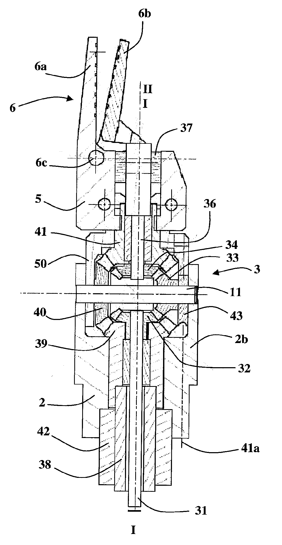
[0073]The working unit 3 comprises a tool support 5 capable of supporting a tool 6. In the figures, a tool 6 has been illustrated in the form of forceps with two arms 6a and 6b.

[0074]The handle 4 comprises control members, for example a first control member 4a, a second control member 4b, a third control member 4c and a forceps control member 4d.

[0075]As in the known devices, the conn...


PUM


Abstract

A manipulator includes a control unit (1), with handle (4) and control buttons (4a-4d), and a connecting arm (2) which, at its proximal end (2a), carries the control unit (1) and, at its distal end (2b), carries a work unit (3). The control buttons (4a-4d) control at least a first inclination motor, which causes a movement of inclination of a tool support (5) of the work unit (3) about a transverse inclination axis (11), and they control the actual rotation of the tool support (5) about its direction of inclination (II) and control the orientation of the direction of inclination (II) about the longitudinal axis (I-I) of the connecting arm (2). A particularly ergonomic manipulator is thus obtained which is easy to learn to use and which efficiently separates the stresses arising from movements of the tool support (5) and the stresses arising from holding and moving the manipulator itself.

Description

TECHNICAL FIELD OF THE INVENTION[0001]The present invention relates to devices for guidance and manipulation, permitting the movements of a manipulation instrument located inside the operating area to be controlled from outside an operating area.[0002]In particular, said devices for guidance and manipulation permit a surgical instrument to be controlled in applications for minimally-invasive surgery carried out by endoscopy.[0003]In said applications, it is necessary to be able to displace and control a surgical instrument to carry out various operations such as providing a suture, tying a knot or delicate dissection of tissue. These are intricate, precise operations in which the movements to be carried out are complex.[0004]Devices for guidance and manipulation by remote-controlled robot have already been proposed, for example the device disclosed in the document U.S. Pat. No. 5,797,900. In this case, a master arm which is able to be actuated by an operator is completely mechanical...

Claims


Application Information

Patent Timeline
Patent Type & Authority Patents(United States)
IPC IPC(8): A61B19/00A61B17/29A61B17/062A61B17/00B25J17/00A61B17/34
CPCA61B2017/291A61B2019/2269A61B2017/2929A61B17/2909A61B19/22A61B2017/00424A61B17/3423A61B17/062A61B2017/2927A61B17/3421Y10T74/20329A61B34/70A61B34/74
Inventor BARRIER, PASCALOLLAGNIER, JEREMYROSSET-LANCHET, REMIMELENNEC EPOUSE BARTHOD, CHRISTINEGIORDANO, MAX
Owner DEXTERITE SURGICAL
Why Eureka
Try Eureka