
Connection assembly having multi-contact connectors with a polarizing system using keys

a multi-contact connector and polarizing system technology, which is applied in the direction of coupling base/case, coupling device connection, incorrect coupling prevention, etc., can solve the problems of not being completely satisfactory, and being unable to provide polarizing at the lateral end using screws as provided in the commercially available assembly, so as to improve the mechanical strength of the keys and improve the mechanical guidance

Active Publication Date: 2014-12-16
RADIALL SA
View PDF11 Cites 19 Cited by
  • Summary
  • Abstract
  • Description
  • Claims
  • Application Information

AI Technical Summary

Benefits of technology

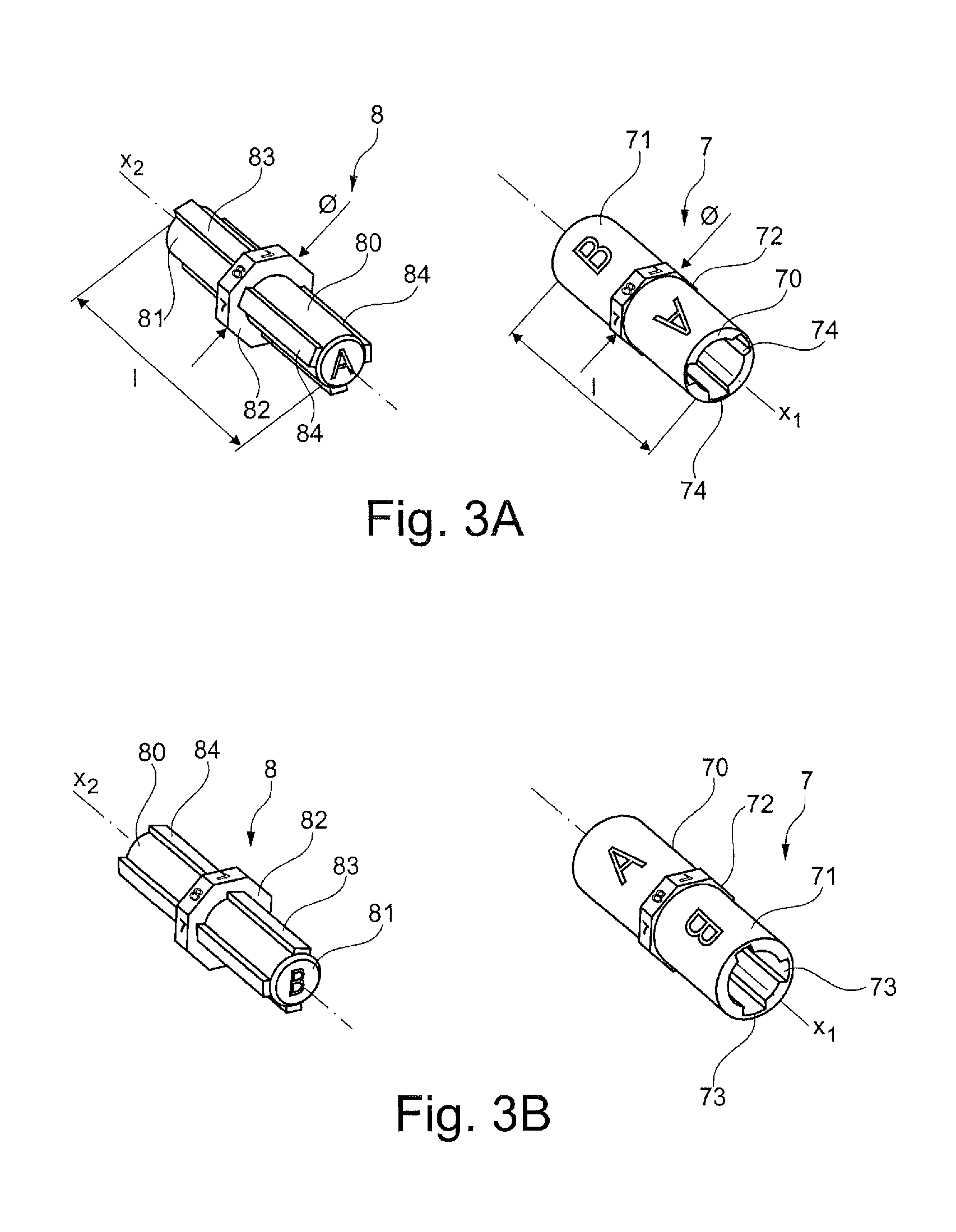
[0013]Because both of the polarizing keys can be engaged reversibly, i.e. via either end portion, the invention thus makes it possible to double the number of coding combinations in a single zone of the connection assembly.
[0033]Preferably, three rectilinear slots are arranged inside the cylinder, the slots being spaced apart from one another in angular positions, and three splines are arranged on the cylinder, being spaced apart from one another in the same angular positions as the slots. It is preferable to define three slots and three corresponding splines since that makes it possible firstly to have better mechanical guidance while coupling together the two polarizing keys, and secondly to have better mechanical strength for the keys in the event of a coupling error.

Problems solved by technology

Nevertheless, it is not completely satisfactory, since it allows the codes to be viewed only from the rear faces of the housings, and above all it always requires an extractor tool to be used in order to remove the polarizing keys from their recesses.
Unfortunately, in its unlocked position, such a cap must come into register with one of the lateral ends of the housings, thus making it impossible to provide polarizing at that lateral end by using screws as provided in the commercially available assembly.

Method used


Image

  • Connection assembly having multi-contact connectors with a polarizing system using keys
  • Connection assembly having multi-contact connectors with a polarizing system using keys
  • Connection assembly having multi-contact connectors with a polarizing system using keys

Examples


first embodiment

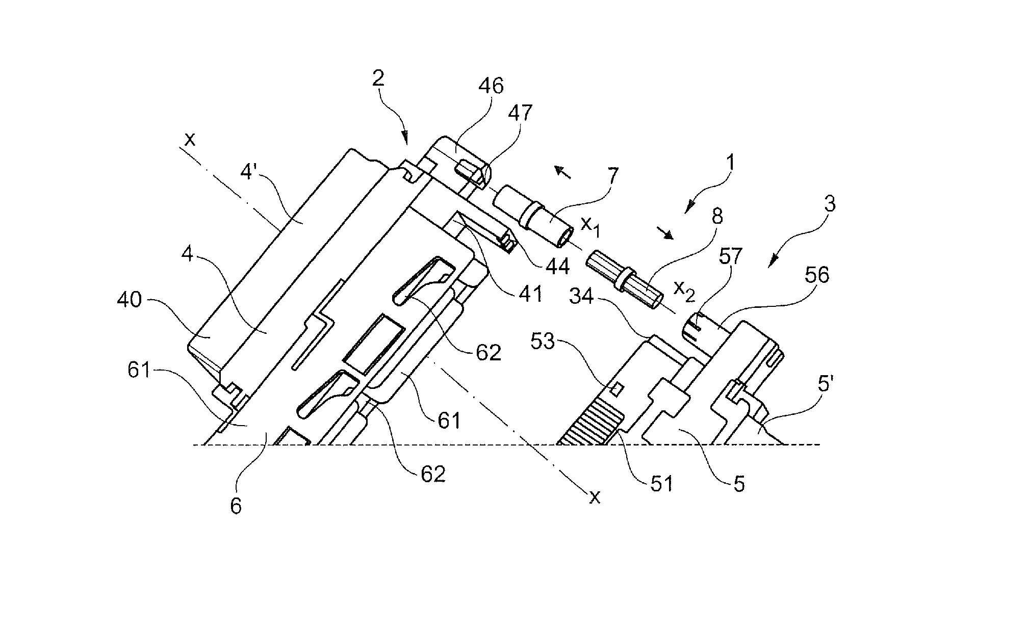
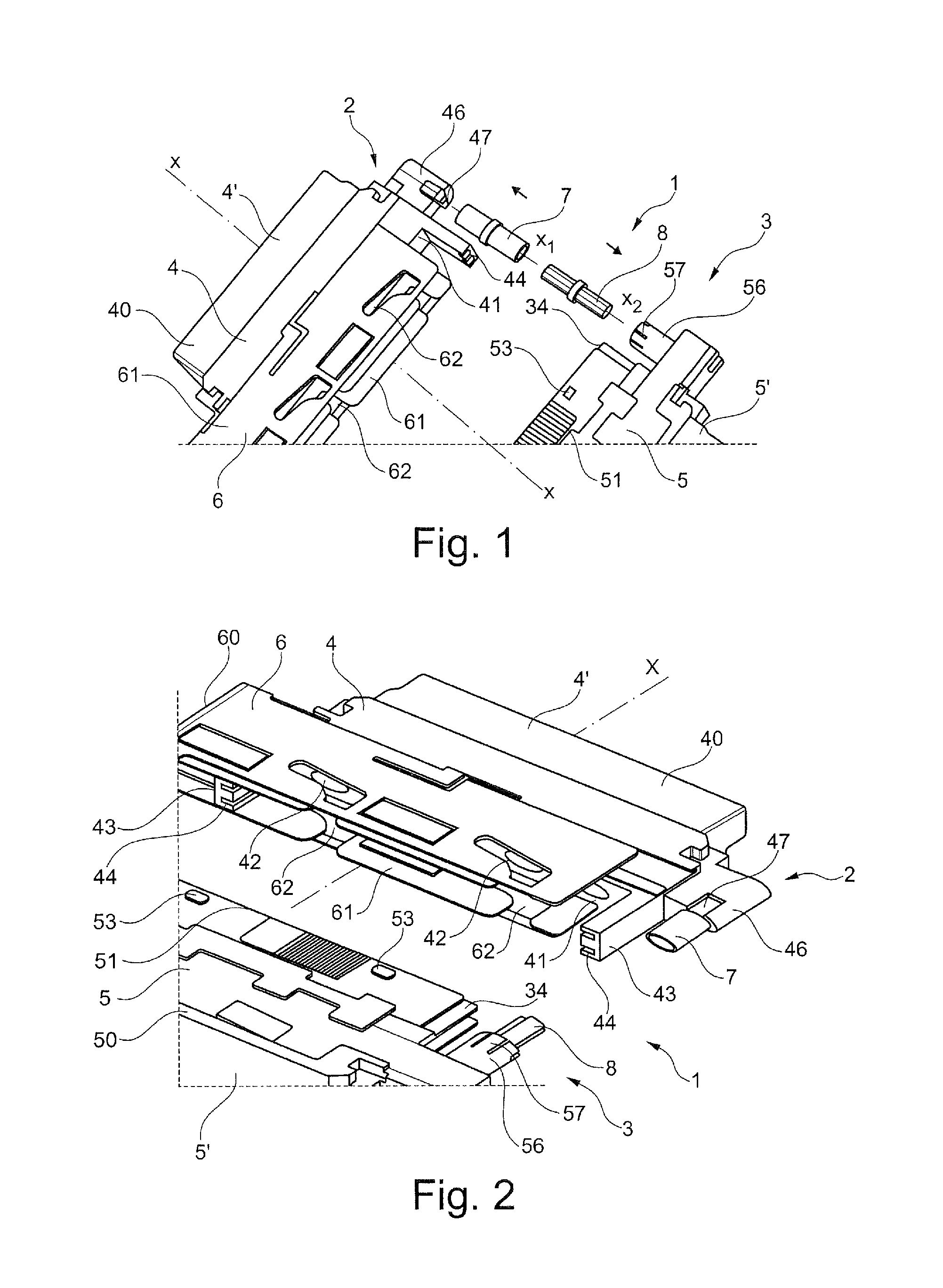
[0049]FIGS. 1, 2, 7, and 8 show a connection assembly given overall reference 1 in the invention. This connection assembly 1 comprises a first multi-contact connector given overall reference 2 and a second multi-contact connector given overall reference 3. The multi-contact connectors 2 and 3 are of complementary type, it being possible, by way of example, for the first connector 2 to be of the male type and in particular to be a plug, while the second connector 3 is of the female type, being in particular a socket.

[0050]However, in all of the figures described, the first connector 2 is a female plug and the second connector 3 is a male socket.

[0051]Each multi-contact connector 2, 3 conveys optical signals, electrical signals, or power. In a variant, signals or power of different types may be conveyed by each of the multi-contact connectors, in which case contacts of different sizes and different types are arranged simultaneously in the connectors.

[0052]The contacts may be single or...

second embodiment

[0120]Also in this second embodiment, the end wall of the recess 46 in the housing 4 is adapted solely to receiving the female key 7 and is fitted with a solid cylinder 9. When the female key 7 is inserted into the recess 46, the solid cylinder 9 penetrates into the inside of one of the end portions 70, 71 without that leading to any problem of assembly. If an attempt is made to insert the male key 8 in the recess 46, the solid cylinder 9 comes into abutment against the male key 8 and thus prevents it from being snap-fastened. The mechanical interference between the solid cylinder 9 and the male key 8 is shown in FIG. 10. In this figure, it can clearly be seen that the male key 8 comes into abutment against the solid cylinder 9.

[0121]Naturally, although FIGS. 8 to 10 show a configuration in which it is impossible to insert the female key 7 in the second connector 3 (socket) or the male key 8 in the first connector 2 (plug), it is naturally possible to provide the inverse configurati...


PUM


Abstract

A connection assembly includes a first connector and a second connector, each with a housing extending along an axis and having a connection face, being connected together via their connection faces. Also included is, at least, one coupled-together pair of polarizing keys, each key being of elongate shape along an axis and projecting from one of the housings beyond its connection face. Each key includes at each one of its ends a portion with a peripheral surface that is provided with at least one projecting and / or hollow shape. Each end portion of one of the two keys is adapted to engage via complementary shapes with a single end portion of the other of the two keys along their coinciding axes and in only one relative angular position between them. Each polarizing key is fastened via one of its end portions to the housing of one of the connectors.

Description

FIELD OF THE INVENTION[0001]The present invention provides a connection assembly comprising multi-contact connectors that are connected together and polarizing keys that enable only the desired connection to be made.BACKGROUND OF THE INVENTION[0002]Patent application EP 1 708 313 in the name of the Applicant discloses a connection assembly comprising a first multi-contact connector and a second multi-contact connector of complementary type. Each connector comprises a housing receiving contacts, and the connection assembly includes a cap enabling the first and second connectors to be locked together.[0003]Another known connection assembly comprising multi-contact connectors is sold by the Applicant under the trade name Amphenol-Air LB—Series 1900. In that connection assembly, in addition to mechanical and electrical connection that is provided via their connection faces, mechanical coupling between the connectors is also provided via polarizing keys in the form of screws F1 and M1 ha...

Claims


Application Information

Patent Timeline
Patent Type & Authority Patents(United States)
IPC IPC(8): H01R13/64H01R13/641H01R13/46H01R13/639H01R13/645
CPCH01R13/465H01R13/64H01R13/639H01R13/641H01R13/6453
Inventor BECAVIN, PATRICE
Owner RADIALL SA
Learn More