
Method and apparatus of multiplexing and acquiring data from multiple optical fibers using a single data channel of an optical frequency-domain reflectometry (OFDR) system

a technology of optical frequency domain reflectometry and optical fiber, applied in the field of optical fiber sensing systems, can solve the problems of complex wiring layout, unsuitable for certain applications, expensive and impractical use of direct line-of-sight monitoring, etc., and achieve the effect of simplifying optical, electronic and computational complexity

Active Publication Date: 2014-12-09
NASA
View PDF10 Cites 42 Cited by
  • Summary
  • Abstract
  • Description
  • Claims
  • Application Information

AI Technical Summary

Benefits of technology

The patent text describes a system and technique that simplifies the complexity of optical, electronic, and computational components in a way that makes it useful for large and distributed structures that need a lot of measurement points. This technique is particularly useful in multiplexed or branched OFS networks. In summary, the patent helps to make it easier to measure and analyze large structures using optical systems.

Problems solved by technology

There are many different sensors and sensing networks for accomplishing this, but many have inherent limitations that render them unsuitable for certain applications.
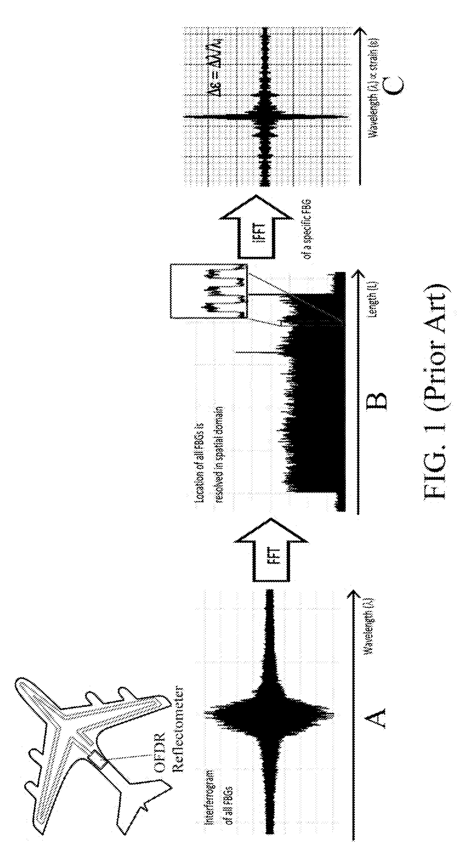
However, this technique requires a clear line of sight, and oftentimes the use of any direct line-of-sight monitoring is either impossible or impractical.
However, these involve complex wiring layouts which are costly and impractical, and indeed the wires tend to corrode and break with age.
Electronics-based sensors are also perpetrators of electromagnetic interference (EMI) which is an undesirable byproduct in a supposedly non-invasive sensing system.
However, it limits the ability to monitor different branched sections.
Should any breakage occur throughout the continuous fiber the entire system is susceptible to loss of data after the breakage.
Monitoring a multiplexed or branched OFS network involving multiple fiber sensing arms each having multiple FBGs along their length is significantly more complicated.
Thus, by way of example, in order to monitor three parallel fiber sections ten feet apart simultaneously, there are currently three solutions: 1) process each fiber section separately (which essentially requires multiple interferometers and computational complexity to interpret the three results); 2) join the three sections together (which adds unnecessary optical fiber increasing system cost and increases the risk of fiber breaking; or 3) multiplexing three segments into one acquisition channel.
This is difficult in the context of a Michelson interferometer system that multiplexes a network of parallel FBG sensor-fibers to a single acquisition channel.
Combining multiple FBG sensor arms results in an equal factor loss in power because optical splitter / coupler inherently loses light.
However, Froggatt '3719 is confined to a fiber-optic imaging system that works in transmission mode for collecting scattered light in multiple fibers at multiple locations.
This approach is unsatisfactory for a system using FBGs in reflectance mode because optical combiners inherently lose light.

Method used


Image

  • Method and apparatus of multiplexing and acquiring data from multiple optical fibers using a single data channel of an optical frequency-domain reflectometry (OFDR) system
  • Method and apparatus of multiplexing and acquiring data from multiple optical fibers using a single data channel of an optical frequency-domain reflectometry (OFDR) system
  • Method and apparatus of multiplexing and acquiring data from multiple optical fibers using a single data channel of an optical frequency-domain reflectometry (OFDR) system

Examples


Embodiment Construction

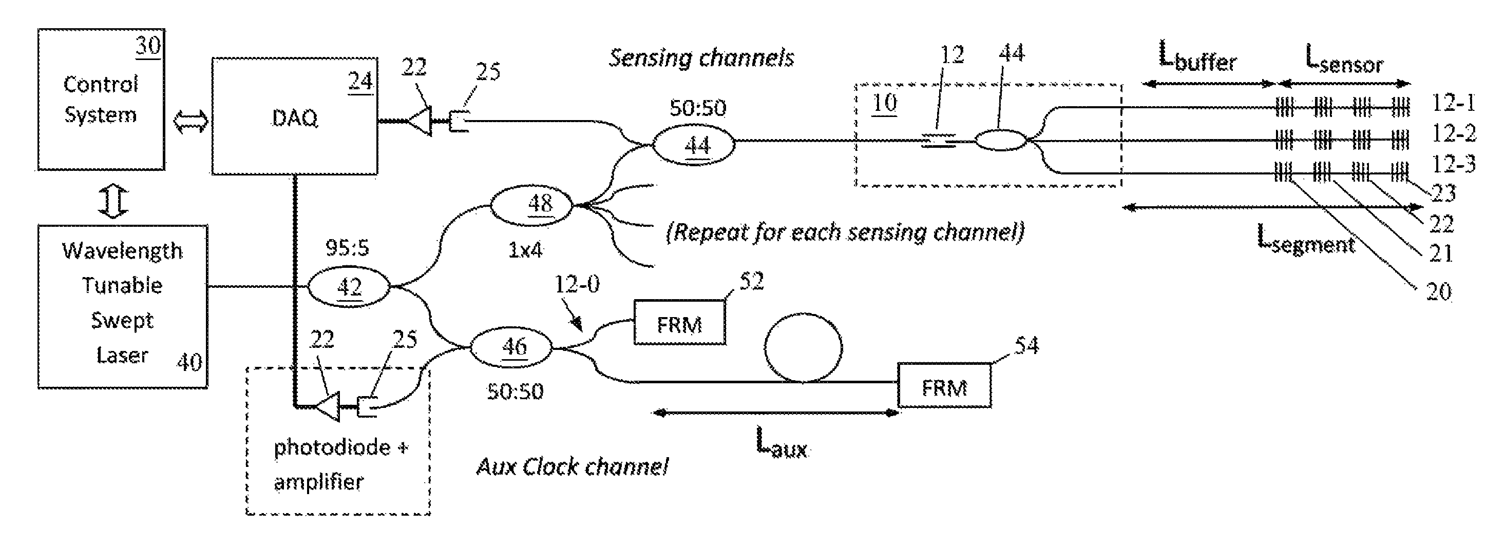
[0028]The present invention is a multi-channel fiber optic sensor system (FOSS) and method for multiplexing a network of parallel fiber Bragg grating (FBG) sensor-fibers to a single acquisition channel of a closed Michelson interferometer system.

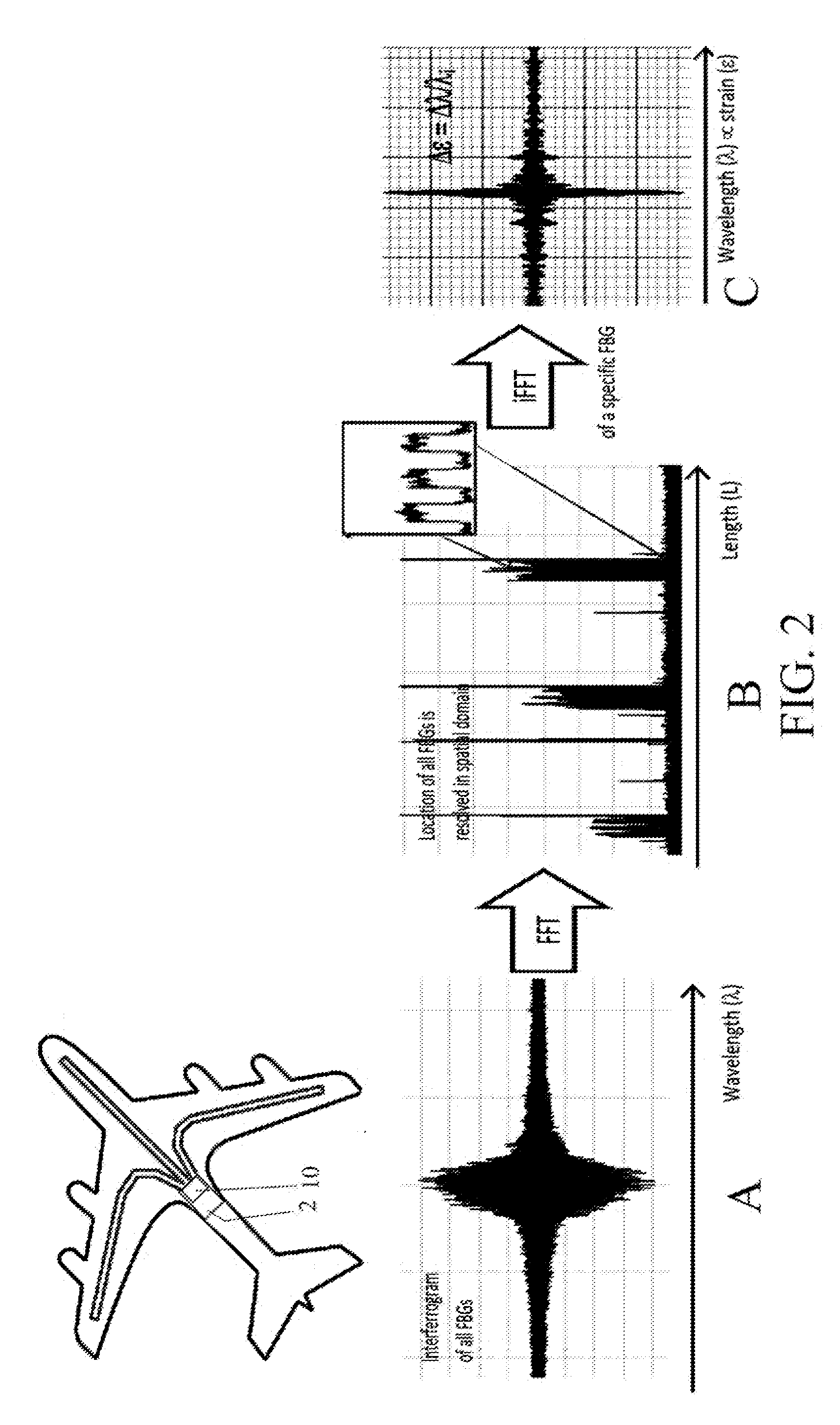
[0029]FIG. 2 is a perspective diagram illustrating a multi-channel FOSS 2 according to the present invention, as well as a new method (A-C) of processing the multiplexed OFDR data from the multiple sensor arms. The FOSS 2 employs a reflectometer with one or more sensing channels (one being shown), each channel being optically multiplexed to multiple parallel sensing fibers (each a “sensing arm”, three of which are shown) to interrogate all locations of interest. The three sensing arms are multiplexed to one sensing channel by a multiplexer 10 which is part of the FOSS 2. As seen at (A) sensor acquisition occurs when all sensing arms are interrogated under OFDR resulting in an interferogram of all FBGs as pictured and described above. As seen...


PUM


Abstract

A method and system for multiplexing a network of parallel fiber Bragg grating (FBG) sensor-fibers to a single acquisition channel of a closed Michelson interferometer system via a fiber splitter by distinguishing each branch of fiber sensors in the spatial domain. On each branch of the splitter, the fibers have a specific pre-determined length, effectively separating each branch of fiber sensors spatially. In the spatial domain the fiber branches are seen as part of one acquisition channel on the interrogation system. However, the FBG-reference arm beat frequency information for each fiber is retained. Since the beat frequency is generated between the reference arm, the effective fiber length of each successive branch includes the entire length of the preceding branch. The multiple branches are seen as one fiber having three segments where the segments can be resolved. This greatly simplifies optical, electronic and computational complexity, and is especially suited for use in multiplexed or branched OFS networks for SHM of large and / or distributed structures which need a lot of measurement points.

Description

STATEMENT OF GOVERNMENT RIGHTS[0001]The invention described herein may be manufactured and used by or for the Government of the United States of America for governmental purposes without payment of any royalties thereon or therefor.BACKGROUND OF THE INVENTION[0002]1. Field of the Invention[0003]The present invention relates to optical fiber sensing systems and, more specifically, to a method and system for multiplexing a network of parallel fiber Bragg grating (FBG) sensor-fibers to a single acquisition channel of a closed Michelson interferometer system via a fiber splitter by distinguishing each branch of fiber sensors in the spatial domain.[0004]2. Description of the Background[0005]There are many diverse engineering applications where determining or monitoring the shape of an article or structure is of paramount importance. The science of determining changes to the material and / or geometric properties of a structure is referred to as Structural Health Monitoring (SHM). Generally...

Claims


Application Information

Patent Timeline
IPC IPC(8): H04J14/02G02B6/35H04B10/071H04B17/00
CPCH04B10/071G02B6/35G01D5/35316G01D5/35387G01M5/0016G01M5/0091G02B6/2932
Inventor PARKER, JR., ALLEN RCHAN, HON MANPIAZZA, ANTHONY NINORICHARDS, WILLIAM LANCE
Owner NASA
Learn More