
Wave energy converter with asymmetrical float

a technology of asymmetrical float and wave energy, which is applied in the direction of control system, machine/engine, sea energy generation, etc., can solve the problems of increased susceptibility to being damaged under storm conditions, significant drawbacks of asymmetrical float use, and increased storm damage, so as to increase the survivability and operability of the wec, reduce the application of excessive, potentially destructive, forces, and increase the effect of energy captur

Active Publication Date: 2014-12-09
OCEAN POWER TECHNOLOGIES
View PDF1 Cites 5 Cited by
  • Summary
  • Abstract
  • Description
  • Claims
  • Application Information

AI Technical Summary

Benefits of technology

[0009]Applicants' invention resides in part in the recognition of the problems discussed above and, in part, in the recognition that, for power conversion efficiency an asymmetrical float should be used. Applicants' invention also resides in the recognition that: (1) the float should be rotated so its long side faces the incoming waves in order to increase energy capture; and (2) the float should be re-oriented (rotated) so its profile to oncoming storm condition waves is decreased in order to reduce the application of excessive, potentially destructive, forces and in order to increase the survivability of the WEC. Thus, WEC systems embodying the invention include means for rotating the WEC as a function of wave conditions.
[0011]A WEC embodying the invention includes an asymmetrical float intended to move generally, up and down, in phase with the waves and a spar which is either stationary or which is designed so that it can move up and down, in phase with the float but with a time delay relative to the float, and / or generally, up and down, out of phase relative to the float. A PTO is connected between the float and spar to convert their relative motion into useful energy (e.g., electric power). The asymmetrically shaped float has a longer side and a narrower side. The WEC includes apparatus for orienting the longer side of the float so it faces the incoming waves for increasing the wave energy conversion efficiency of the WEC and for orienting the float so its narrower side faces the incoming waves under storm conditions to improve the survivability of the WEC.
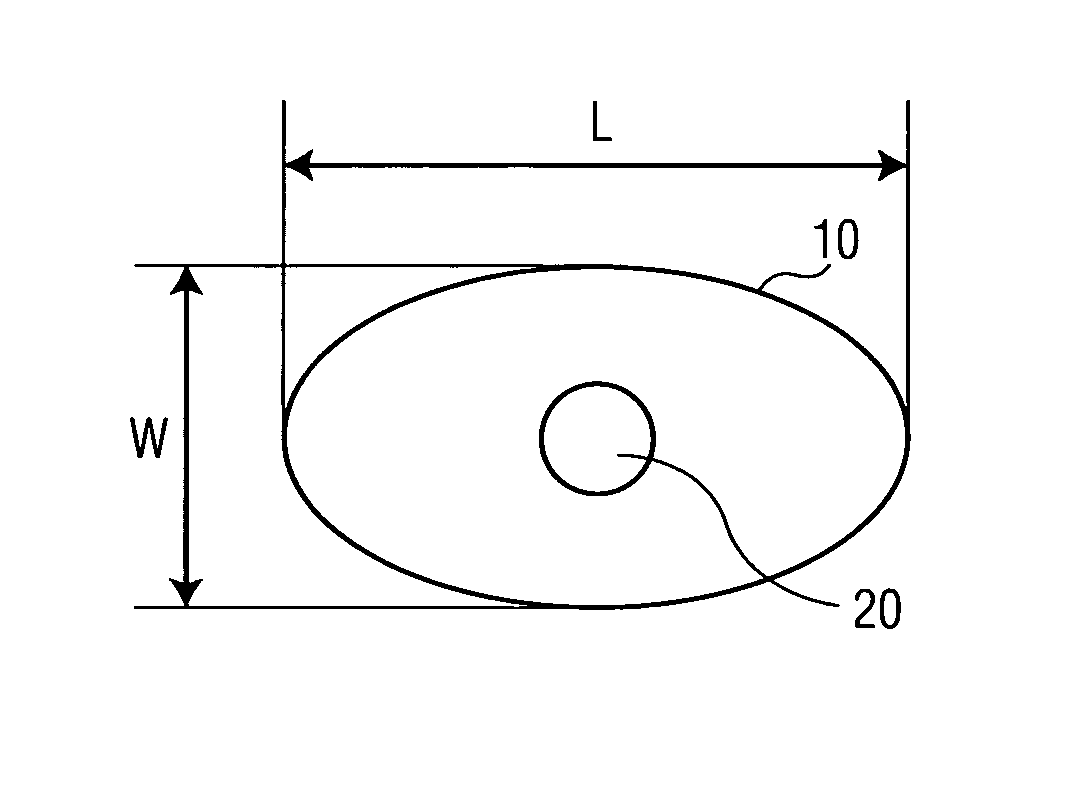
[0012]The float has top and bottom surfaces which extend generally parallel to the water surface and the float moves up and down generally in-phase with the waves. The spar extends in a direction generally perpendicular to the surface of the water. The float is “asymmetrical” (e.g., rectangular or oblong). That is, the float will have a “longer” (or “beam”) side and a “narrower” (“shorter” or “head”) side; its length (L) will be greater than its width (W). The longer side is designed to normally face the incoming waves to improve the power conversion efficiency of the WEC to incoming waves whose frequency and wavelength is within a predetermined range.
[0014]To reduce excessive stresses to which the WEC may be subjected during storm conditions, WECs embodying the invention include means for selectively, or automatically, (e.g., actively or passively) re-orienting the asymmetrical float so that during “normal” operating conditions the long side of the float faces the incoming waves and during a “storm” condition the shorter, narrower, side faces the incoming waves. Thus, the long side of the float will be turned towards the waves under those conditions where it is desired to produce power, and the short side of the float will be turned towards the waves under storm conditions to reduce stresses to which the WEC may be subjected.

Problems solved by technology

However, Applicants recognized that a significant drawback exists to the use of the asymmetrical float because: (1) the direction of the incoming waves may vary undoing the benefits sought; and (2) it has greater susceptibility to being damaged under storm conditions.
However, under storm conditions where the wave amplitudes are greater than normally expected (e.g., the waves have amplitudes greater than 4 meters) greater buoyant forces are applied to the asymmetrical float and significantly higher forces are developed between the float and spar tending to damage the WEC and its PTO.
Thus, while it is desirable to have the long side of an asymmetrical float facing incoming waves for improved wave energy conversion, there is a problem with the survivability and operability of the WEC under storm and varying wave conditions.

Method used


Image

  • Wave energy converter with asymmetrical float
  • Wave energy converter with asymmetrical float
  • Wave energy converter with asymmetrical float

Examples


example

[0046]In very long waves the decrease in wave forcing is small if the float is rotated (small because the wave is so long.) However, there will be less force on the bearings, so that could have a net improvement on power.

[0047]The control apparatus 400 encompasses the means to change and control the orientation of float 10. The apparatus 400 may be an active system or a passive system or a hybrid system. Also, the apparatus 400 may be designed to cause the float 10 to rotate incrementally or in a continuous manner over a wide angular range.

[0048]One embodiment of the apparatus is shown in a highly simplified block form in FIG. 4. Various wave conditions may be sensed and processed, and based on the processed information and predetermined data, the float and / or the spar may be rotated to re-orient the float with respect to the direction of the incoming waves.

[0049]FIG. 4 illustrates that many different sensors may be used to sense the condition of the waves and provide their signals ...


PUM


Abstract

A wave energy converter (WEC) having an asymmetrically shaped float and a spar which move relative to each other in response to the waves. The asymmetrical float has one side longer than the other. A power take off device (PTO) is coupled between the asymmetric float and the spar for converting their relative motion into useful power. Apparatus is coupled to the WEC for: (a) orienting and rotating the longer side of the float to face and receive oncoming waves to increase energy capture when the waves have an amplitude below a predetermined value for improving the power generation of the WEC; and (b) rotating the float to orient the narrower side of the float to face and receive the incoming waves when the waves have an amplitude above a predetermined value, so as to reduce the forces to which the WEC is subjected.There is no known WEC system with an asymmetrical float which is raised and lowered by the waves.

Description

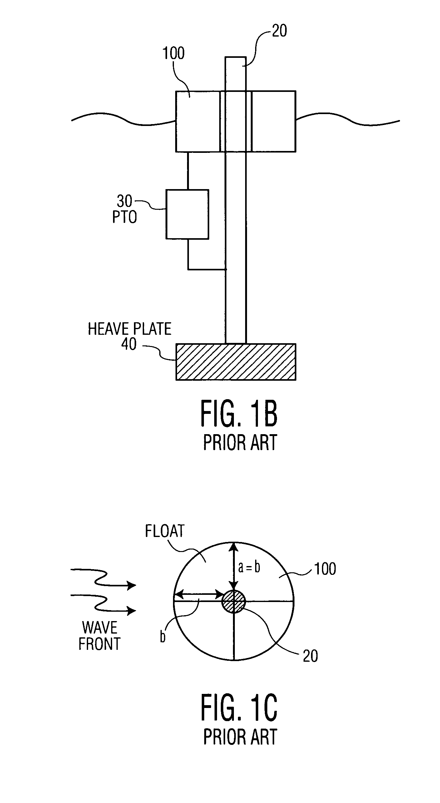
BACKGROUND OF THE INVENTION[0001]This invention relates to a wave energy converter (WEC) designed to provide improved efficiency under normal operating conditions and to have improved survivability to large amplitude waves.[0002]A WEC, as shown in FIGS. 1A and 1B, may include a float 100 and a shaft / spar 20 with a power take off device (PTO), 30, connected between the float and shaft. The float is generally designed to move in synchronism with the waves. The shaft 20 may be designed to be stationary (e.g., anchored to the sea bed as shown in FIG. 1A) or it may be designed so that it can move up and down, in phase with the float but with a time delay relative to the float and / or generally out of phase with the waves and the float, as shown in FIG. 1B, in a configuration which may be referred to as a “dual absorber”. In any case, the PTO is connected between the shaft and the float for converting their relative motion into useful energy (e.g., electrical power or different forms of me...

Claims


Application Information

Patent Timeline
Patent Type & Authority Patents(United States)
IPC IPC(8): F03B13/18
CPCF03B13/1855F05B2250/14Y02E10/38F05B2250/73F05B2270/103F05B2250/141Y02E10/30
Inventor GERBER, JAMES S.TAYLOR, GEORGE W.
Owner OCEAN POWER TECHNOLOGIES
Learn More