
Variable strength magnetic end effector for lift systems

a technology of end effectors and magnetic end effects, which is applied in the direction of instruments, program control, and wellbore/well accessories, etc., can solve the problems of many of the end effectors, when active, deficient in their functionality, and consider the problems of not being safe, efficient and/or cost effectiv

Active Publication Date: 2014-11-18
SARCOS LC
View PDF92 Cites 33 Cited by
  • Summary
  • Abstract
  • Description
  • Claims
  • Application Information

AI Technical Summary

Benefits of technology

Enables efficient and precise lifting and transporting of specific payloads by allowing infinite adjustment of magnetic force, overcoming the limitations of conventional systems that only operate at full power or no power, thereby improving safety and efficiency.

Problems solved by technology

Lifting and transporting specific types of objects and items from one location to another often presents considerable problems in terms of not being safe, efficient and / or cost effective.
However, many of these end effectors, when active, are deficient in terms of their functionality where a payload of a specific weight or a specific amount of payload is required or desired to be transported from one location to another.

Method used


Image

  • Variable strength magnetic end effector for lift systems
  • Variable strength magnetic end effector for lift systems
  • Variable strength magnetic end effector for lift systems

Examples


Embodiment Construction

[0018]The present invention is related to copending nonprovisional U.S. patent application Ser. No. 13 / 332,165, filed Dec. 20, 2011, and entitled, “Teleoperated Robotic System”; Ser. No. 13 / 332,152, filed Dec. 20, 2011, and entitled, “System and Method for Controlling a Tele-Operated Robotic Agile Lift System”; Ser. No. 13 / 332,138, filed Dec. 20, 2011, and entitled, “Platform Perturbation Compensation”; Ser. No. 13 / 332,146, filed Dec. 20, 2011, and entitled, “Robotic Agile Lift System with Extremity Control”; Ser. No. 13 / 332,129, filed Dec. 20, 2011, and entitled, “Multi-degree of Freedom Torso Support for Teleoperated Robotic Agile”, each of which is incorporated by reference in its entirety herein.

[0019]As used herein, the singular forms “a,” and, “the” include plural referents unless the context clearly dictates otherwise.

[0020]As used herein, the term “substantially” refers to the complete or nearly complete extent or degree of an action, characteristic, property, state, structu...


PUM

PropertyMeasurementUnit
weightaaaaaaaaaa
weightaaaaaaaaaa
weightaaaaaaaaaa

Abstract

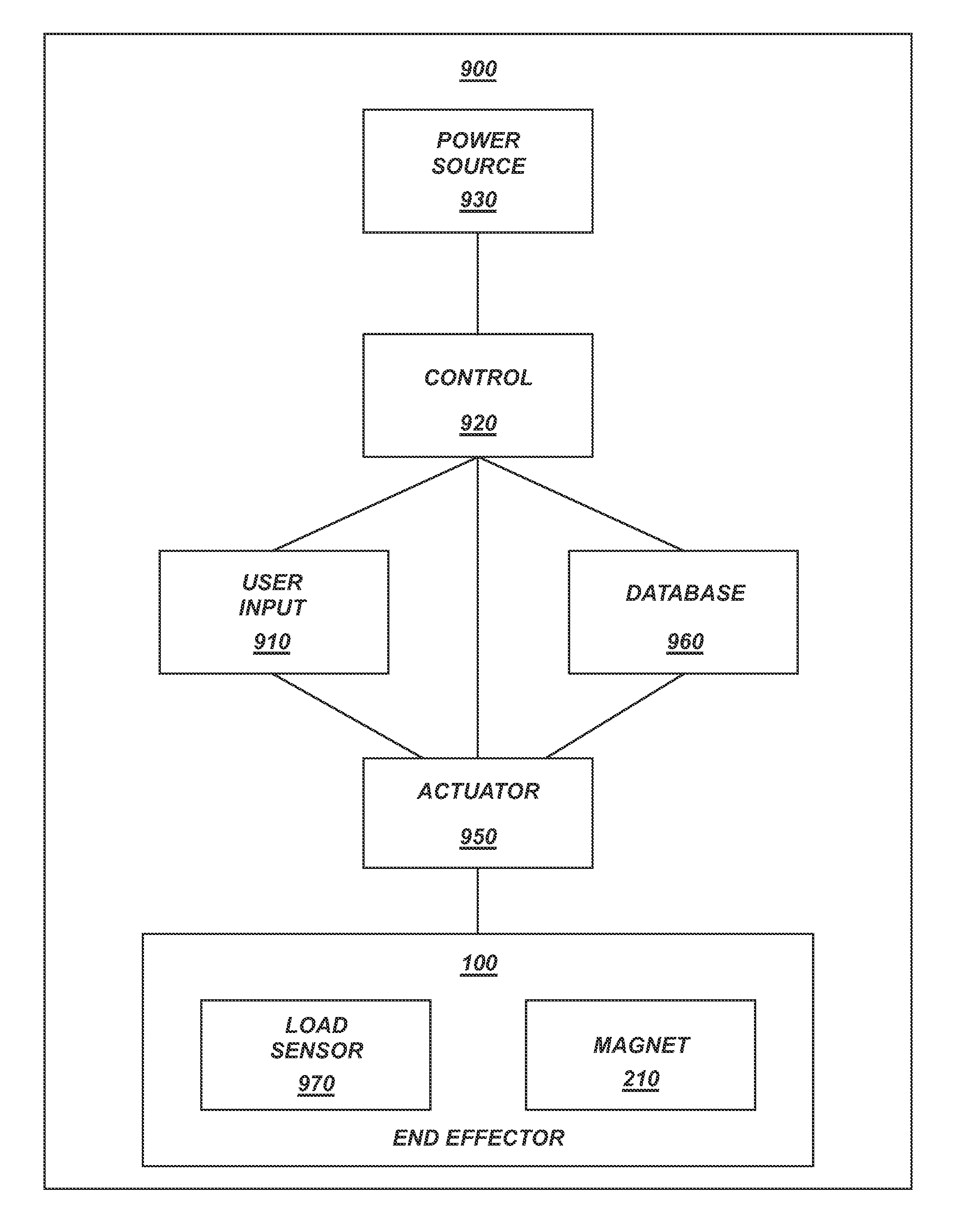
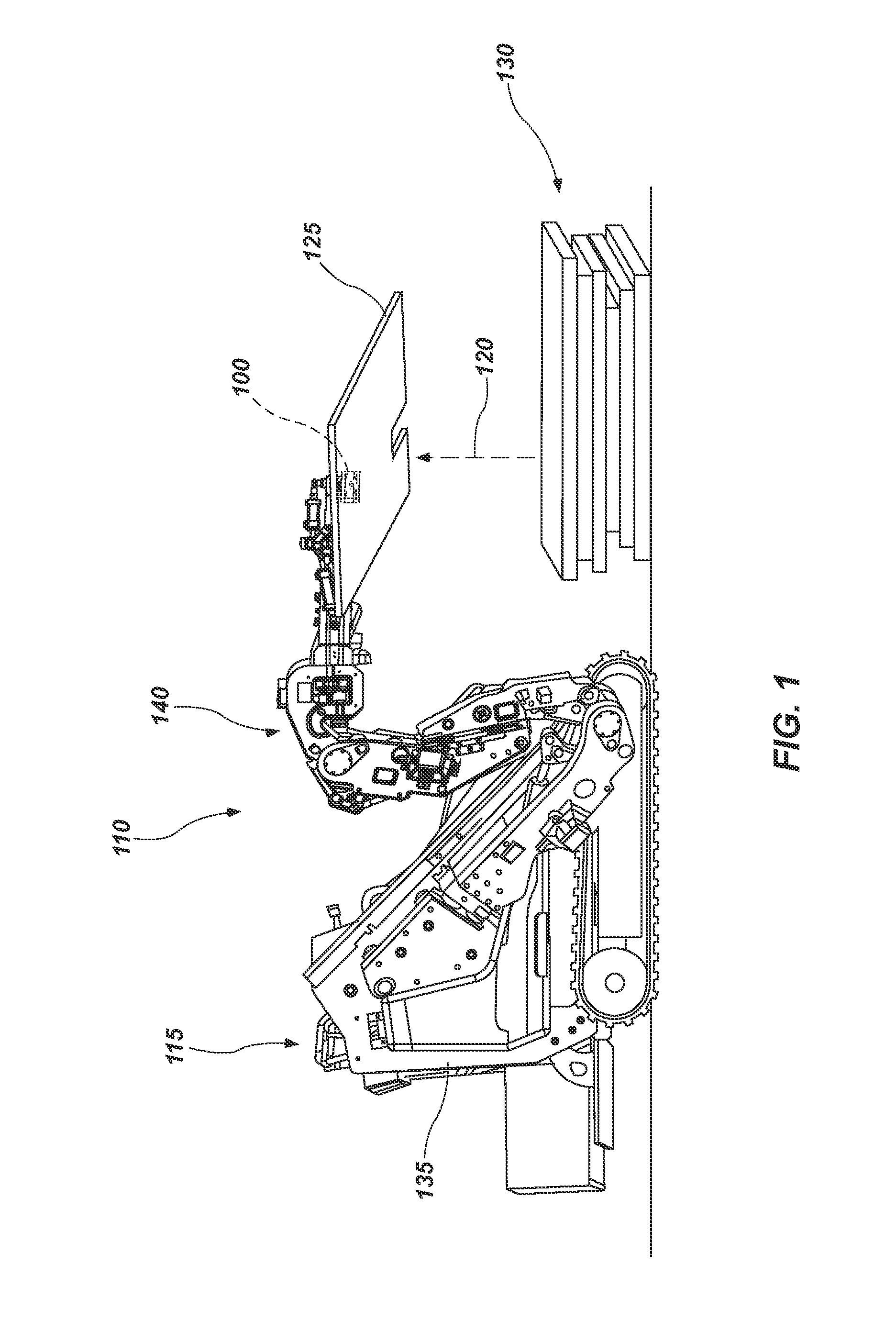
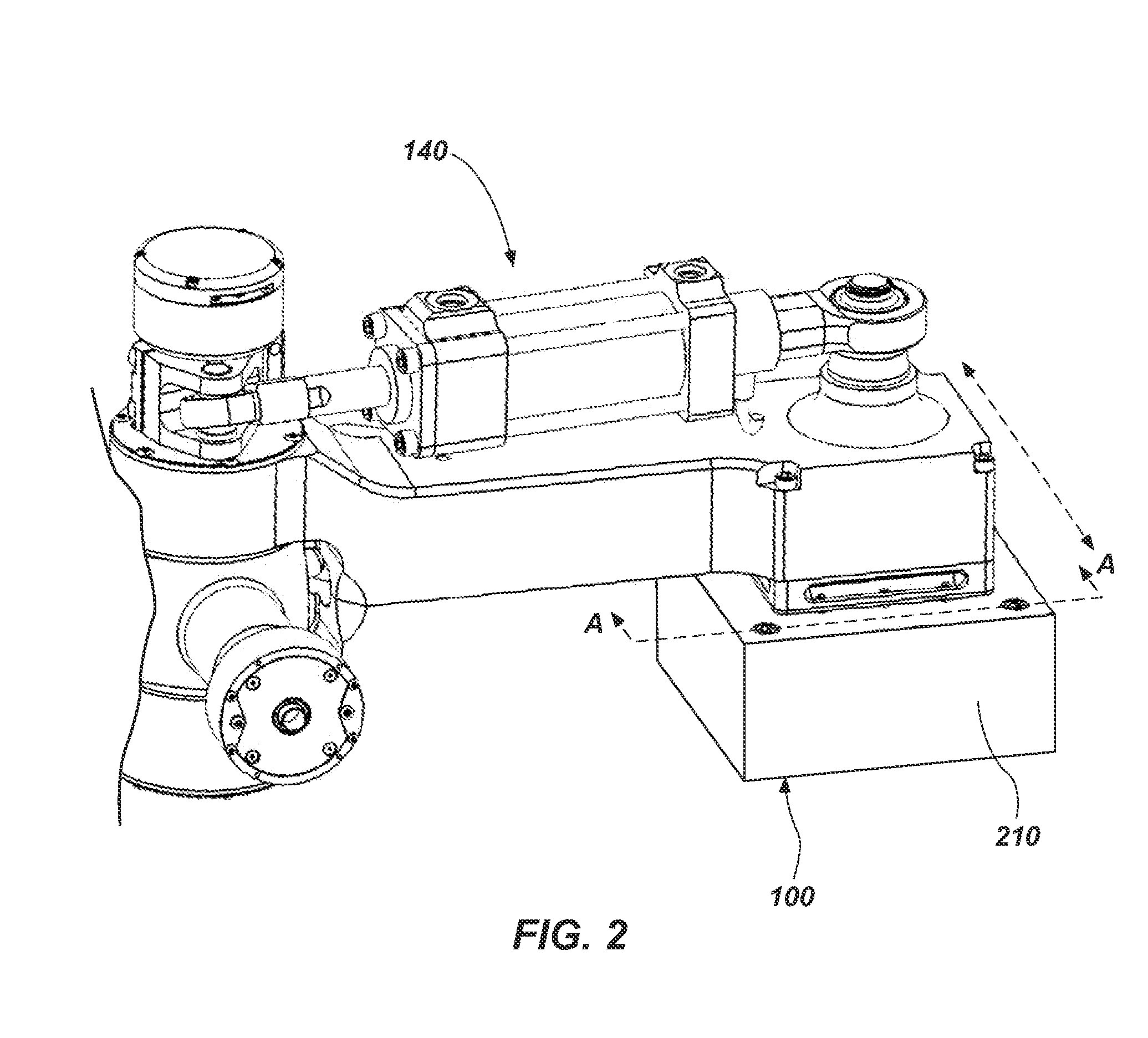
A device and method for adjusting the magnetic strength of a magnetic end effector for lift systems is described. The magnetic end effector is capable of lifting discriminate payloads by selectively varying the strength of the magnetic forces output by the magnetic end effector. An actuator can be operatively coupled to the variable strength magnet end effector, wherein the actuator is selectively actuatable to control the adjustment of the variable strength magnet. The actuator may also be configured to maintain the variable strength magnet at a desired magnetic force output strength once achieved for any given amount of time.

Description

PRIORITY DATA[0001]This application claims the benefit of U.S. Provisional Application Ser. No. 61 / 481,091, filed Apr. 29, 2011, which is incorporated by reference herein in its entirety. This application also claims the benefit of U.S. Provisional Application Ser. No. 61 / 481,110, filed Apr. 29, 2011; 61 / 481,103, filed Apr. 29, 2011; 61 / 481,089, filed Apr. 29, 2011; 61 / 481,099, filed Apr. 29, 2011; and 61 / 481,095, filed Apr. 29, 2011, each of which are incorporated by reference herein in their entirety.BACKGROUND[0002]Lifting and transporting specific types of objects and items from one location to another often presents considerable problems in terms of not being safe, efficient and / or cost effective. Moreover, conventional lifting and transporting systems using one or more end effectors are typically configured to perform a specific function with little variability regarding the capabilities of the end effector.[0003]It is not uncommon for operator controlled lift and / or transport...

Claims


Application Information

Patent Timeline
Patent Type & Authority Patents(United States)
IPC IPC(8): B25J9/16B25J5/00B25B11/00H01F7/04B25J9/00B66C1/04B66C1/68
CPCB25J9/0084H01F7/04B66C1/04B25J5/007B25J9/162B66C1/68B66F9/182B25J11/00B25J13/08B25J15/0608Y10T483/1726
Inventor JACOBSEN, STEPHEN C.SMITH, FRASER M.COLVIN, JR., GLENNMCCULLOUGH, JOHN
Owner SARCOS LC
Learn More