
Light emitting device system and driver

a technology of light emitting devices and drivers, applied in the direction of electric variable regulation, process and machine control, instruments, etc., can solve the problems of not being able to drive the lamps accordingly, and achieve the effect of reducing the power consumption of the system and the power consumption of the driver

Inactive Publication Date: 2014-11-18
KONINK PHILIPS ELECTRONICS NV +1
View PDF10 Cites 3 Cited by
  • Summary
  • Abstract
  • Description
  • Claims
  • Application Information

AI Technical Summary

Benefits of technology

The patent describes a method for controlling a light emitting device system using a driver that captures sensed information about the system via its supply terminals. This eliminates the need for additional signal connections and reduces the risk of malfunctions due to loose contacts. The sensed information can be modulated using a resistor, which can be turned on or off to control the electrical loading of the system. The emulation of impedance allows for dynamic adjustment of the electrical loading and has minimal impact on the power path of the system. The use of different frequency ranges allows for more intelligent detection of the driver's signaling method, reducing power consumption in case of low-end drivers. The driver can switch between two operation modes to optimize power consumption, with the detector circuit disabled in one mode and enabled in another. Overall, this invention provides a cost-effective and efficient solution for light emitting device systems.

Problems solved by technology

However, this allows only for the detection of an identity of an LED unit, not a dynamic adaptation of the characteristics of the supplied power depending on the actual requirements of the LED lamp.
This system lacks the ability to drive the lamp accordingly under different operation conditions of the lamp.

Method used


Image

  • Light emitting device system and driver
  • Light emitting device system and driver
  • Light emitting device system and driver

Examples


first embodiment

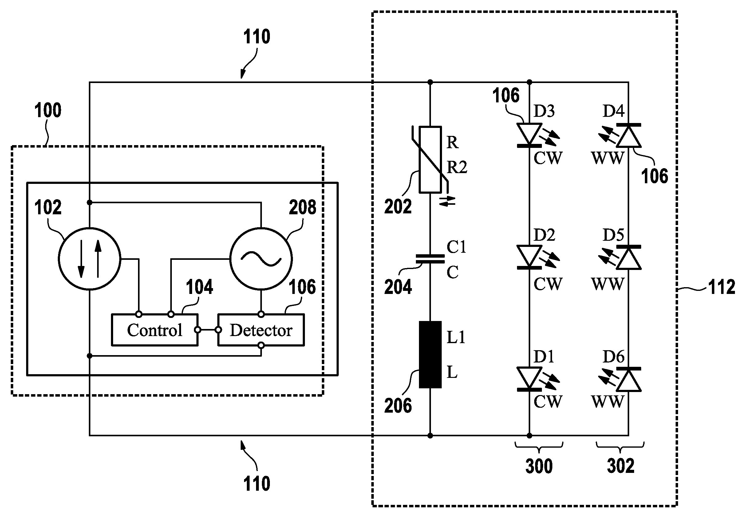
[0057]In a first embodiment, depending on the selected frequency range for supplying power to the light emitting diodes and a selected range for emulating and sensing the impedance, it is possible to omit the voltage source for sensing: in the circuit shown in FIG. 3, the polarity of the drive current is reversed in a certain sequence, usually at a high rate to avoid flickering of the light emitting diodes. These drive current pulses can be designed to incorporate a dedicated frequency spectrum which can be used to replace the voltage source 208.

second embodiment

[0058]In a second embodiment, it is possible to use the voltage source 208 for modulating the output current of the power source 102. The power source 102 can be controlled by means of the controller 104. This was already discussed with respect to FIG. 2. The only difference is that in the embodiment of FIG. 3 the controller 104 can control both the power source 102 and the voltage source 208.

[0059]It has to be noted that the light emitting device system 112 may comprise more than only one sensor. These sensors can be used to detect sequentially different operating conditions of the light emitting device system 112. In a further embodiment of the invention, the emulation circuits influenced by the sensed operating conditions may be tuned to provide the sensed information to the driver at different detection conditions, e.g. at different frequencies or different polarities.

[0060]According to the previous embodiments, the sensor signal has a detectable impact when measuring the loadin...


PUM


Abstract

The invention relates to a driver (100) for a light emitting device system (112), comprising power supply terminals (108) and a detector circuit (106), the power supply terminals being adapted for supplying electrical power from the driver (100) to the light emitting device system and the detector circuit being adapted for capturing sensed information of the light emitting device system via the supply terminals by sensing an electrical loading of the terminals caused by the light emitting device system and for determining an operating condition of the light emitting device system, using the sensed information, wherein the driver is further adapted to control the supplied power depending on the determined operating condition.

Description

TECHNICAL FIELD[0001]The invention relates to a driver for a light emitting device system and a light emitting device system.BACKGROUND AND RELATED ART[0002]Solid State Light (SSL) sources such as, but not limited to, light emitting diodes (LEDs) will play an increasingly significant role in general lighting in the future. This will result in more and more new installations being equipped with LED light sources in various ways. The reason for replacing state of the art light sources with LED light sources is e.g. the lower power consumption of LED light sources and their extremely long lifetime.[0003]Typically, an LED is driven by means of a special circuit, which is called the driver. In order to permit the operation of different kinds of LED light sources with a given driver to come to a more or less modular system, it is desirable that LED lamps are able to communicate their required supply power characteristics to the driver. This allows replacing the LED lamp with a newer versi...

Claims


Application Information

Patent Timeline
Patent Type & Authority Patents(United States)
IPC IPC(8): H05B33/08H05B37/02H05B44/00
CPCH05B33/0821H05B37/0263H05B33/0851H05B47/185H05B45/42H05B45/18H05B45/10H05B45/37
Inventor RADERMACHER, HARALD, JOSEF, GUNTHER
Owner KONINK PHILIPS ELECTRONICS NV
Learn More