
System and method for protecting an electrical power grid

a technology for electrical power networks and systems, applied in the direction of air-break switches, relays, transportation and packaging, etc., can solve the problems of complex construction of multi-ended power networks, increased costs when the number of power generators is increased, and achieve the effect of facilitating fault detection

Active Publication Date: 2014-11-11
HITACHI ENERGY LTD
View PDF12 Cites 0 Cited by
  • Summary
  • Abstract
  • Description
  • Claims
  • Application Information

AI Technical Summary

Problems solved by technology

Such multi-ended power networks are complex constructions and require a number of protection devices.
Arranging protection equipment in this way and having a circuit breaker in both ends of each cable requires a lot of equipment if such a protection system is arranged at a wind power plant having many power generators.
This kind of protection adds costs when the number of power generators, and cables from the power generators are increased in order to scale up the wind power plant.

Method used


Image

  • System and method for protecting an electrical power grid
  • System and method for protecting an electrical power grid
  • System and method for protecting an electrical power grid

Examples


Embodiment Construction

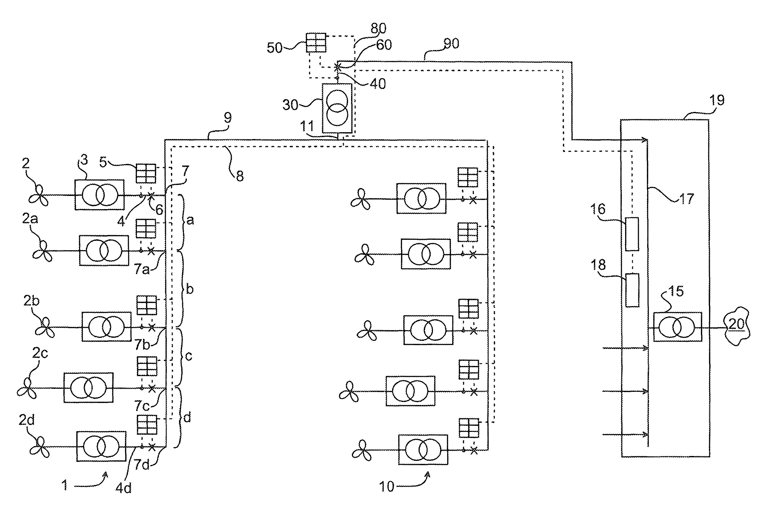
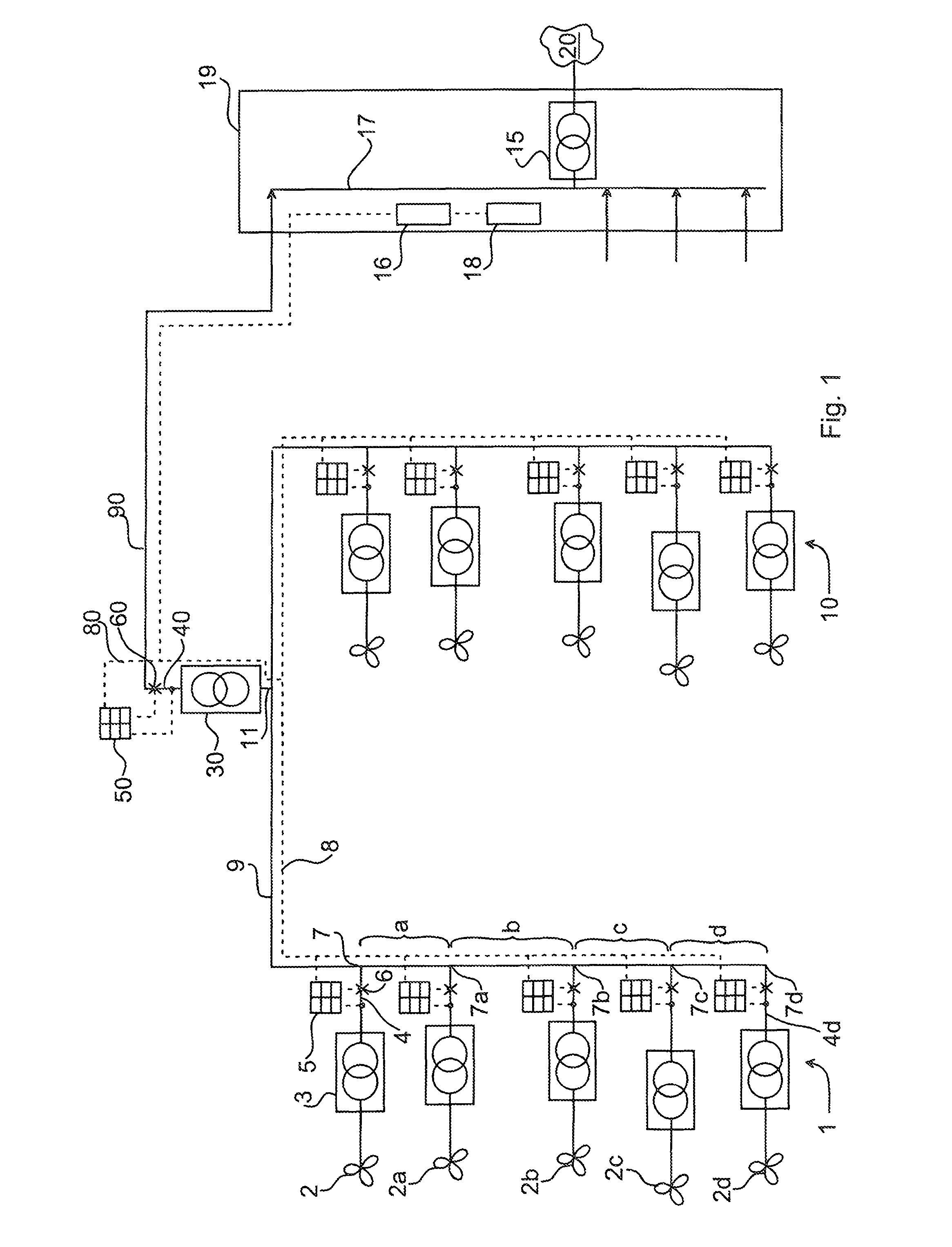
[0049]The invention provides the possibility to protect multi-ended cable networks in a similar way as with a bus bar protection, i.e. an algorithm based on Kirchhoff's law is used to detect if there is a fault inside the cable network.

[0050]The protection function may be based on phasor comparison of time tagged current vectors in all ends. If the sum of all vectors is zero, there is no fault in the cable network.

[0051]For example the multi-ended protection can be based on Phasor measuring units, wherein time tagged samples or phasors are sent over communication links. The sensitivity and selectivity of the applicable function is depending on accurate time-tagging, which can be achieved by so called Echo-timing or by GPS time tagging at each individual end.

[0052]If the sum deviates from zero (+−inaccuracy of measurement data), a fault is detected.

[0053]The invention is adapted for protecting systems with cables and transformers inside the protected zone of the system and additional...


PUM


Abstract

A differential protection system including a plurality of inputs power cables for transfer of power from electric power generators, such as wind power generators, to an output cable. Each input and output power cable is provided with a respective circuit breaker. The protection system includes a plurality of protection equipment unit each being adapted to be arranged at a respective one of the input cables or at the output cable, each protection equipment unit including a measuring unit for measuring the current and voltage of the cable, and including a control unit being operatively connectable to the circuit breaker of the respective power cable for selectively tripping the circuit breaker when the protection system discovers a differential fault. The protection system includes a charging current compensator for compensating the differential protection for charging currents of the cables of the transfer system.

Description

FIELD OF THE INVENTION[0001]The invention relates to methods and arrangements for protection of electrical power networks, especially cable networks for windmill farms.BACKGROUND OF THE INVENTION[0002]Windmill Farms[0003]Windmill farms, or wind power plants, are normally designed to generate power at low voltage or medium voltage. When the generator is generating at low voltage (typically <1000 V) a step-up transformer on board the windmill is used to increase the generated voltage to typically 12-36 kV to reduce the cable size (and cost). A medium voltage generator, typically 12 kV, is an alternative which eliminates the need for a step-up transformer onboard the windmill.[0004]The power from the windmill farm is normally collected in a windmill transformer substation, either underwater, or on a supporting structure above the water level (or on land).[0005]The windmill substation can collect the power from a cluster of windmills and further step up the voltage to reduce cable co...

Claims


Application Information

Patent Timeline
Patent Type & Authority Patents(United States)
IPC IPC(8): H01H31/34
CPCH02H3/283H02H3/28H02H1/043H02H3/30H02H7/261
Inventor LUNDQVIST, BERTIL
Owner HITACHI ENERGY LTD
Learn More