
Variably configurable and modular local convergence point

a local convergence point and variable configuration technology, applied in the field of fiber optic terminals, can solve the problems of lack of features and design of current fiber optic terminals, and achieve the effect of convenient access

Active Publication Date: 2014-11-04
CORNING OPTICAL COMM LLC
View PDF593 Cites 25 Cited by
  • Summary
  • Abstract
  • Description
  • Claims
  • Application Information

AI Technical Summary

Benefits of technology

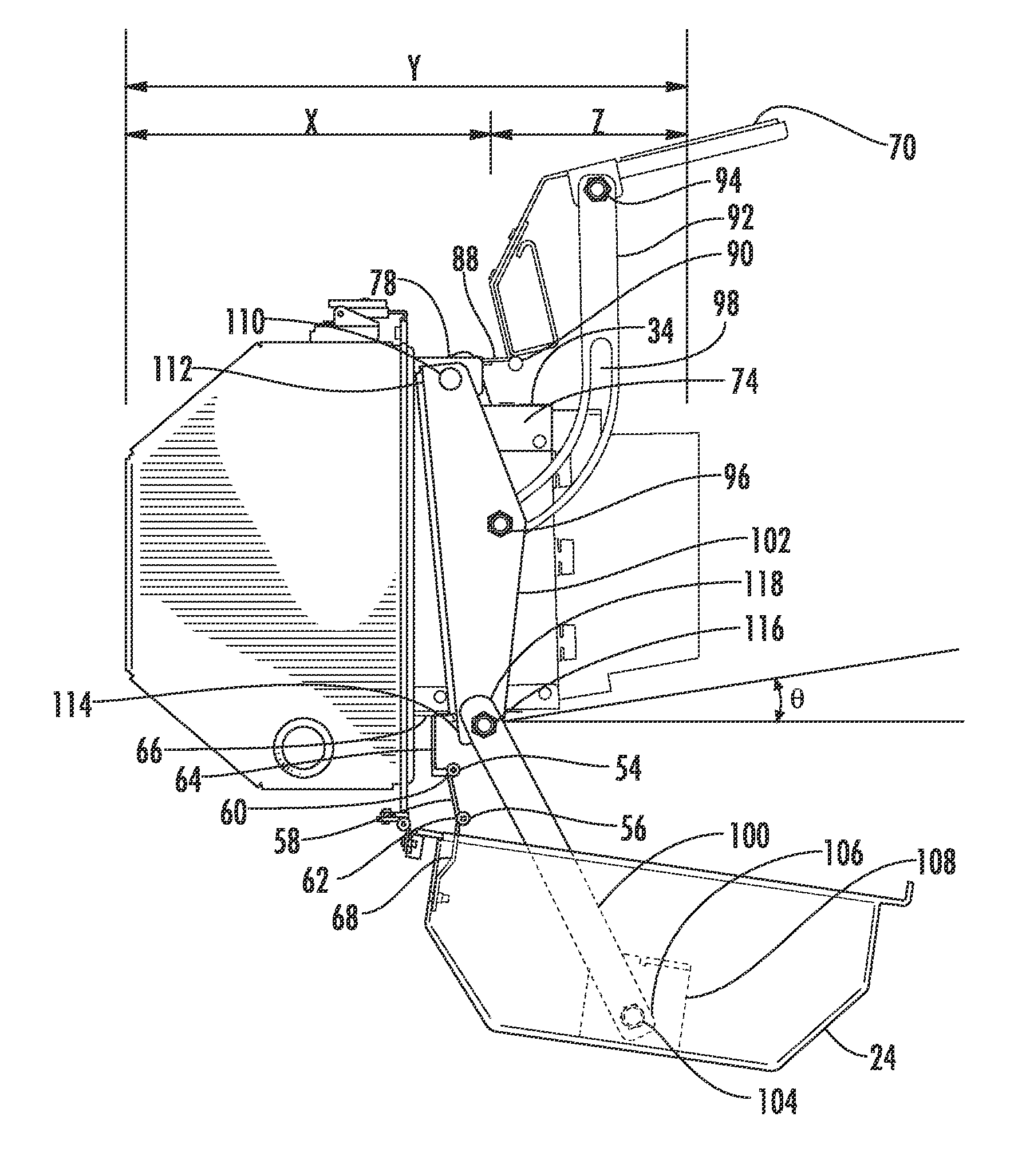
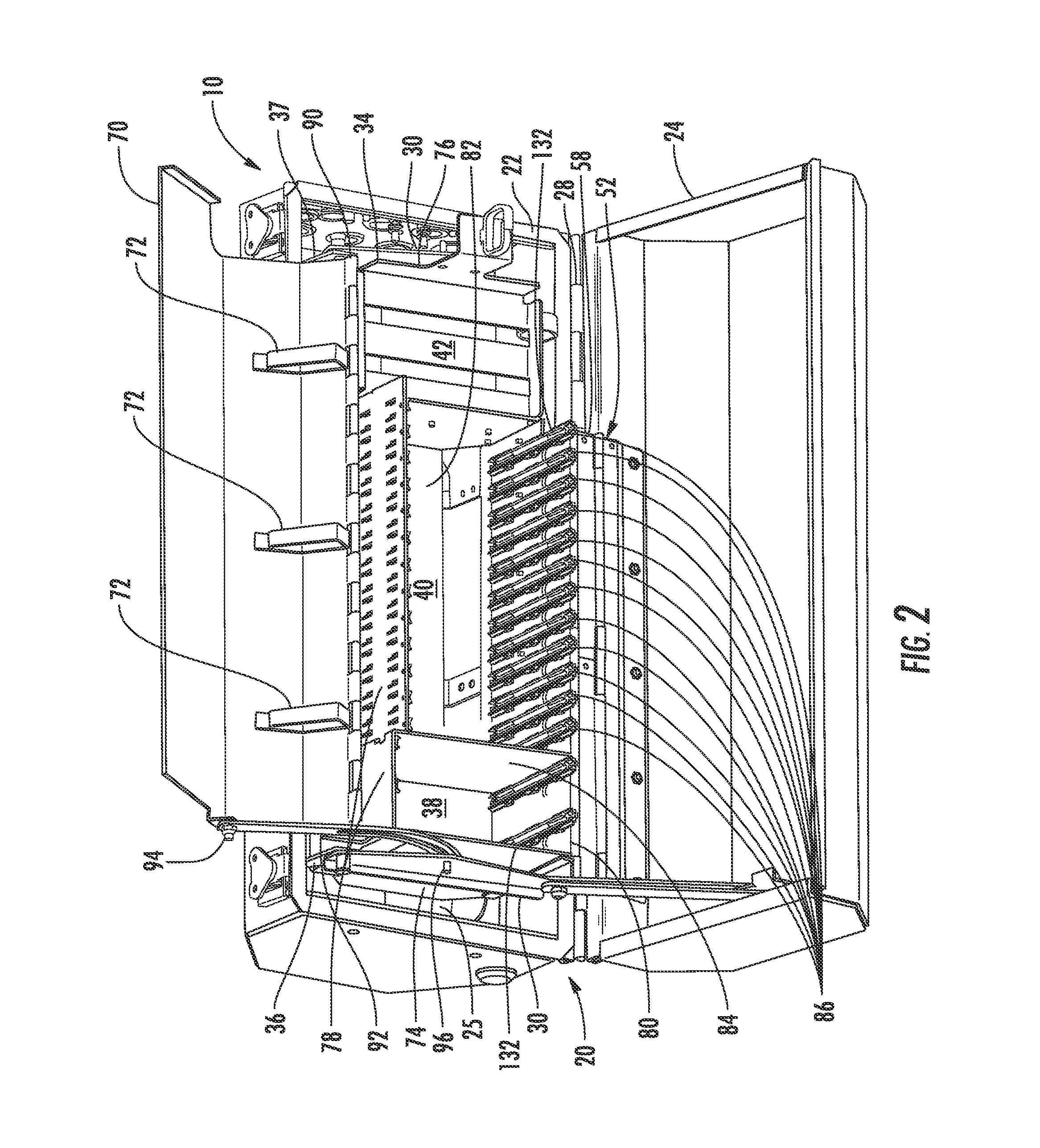
[0007]When the enclosure is closed, the movable chassis positions in the first position. In the first position, the movable chassis positions in the base adjacent to a back of the base. When the enclosure is opened, the movable chassis automatically moves from the first position to the second position In the second position, the movable chassis is partially extended from the base and tilted away from the cover. The second position facilitates access to the cassettes and the splitter modules. Also when the enclosure is open, the movable chassis may position in the third position. In the third position, the movable chassis positions in the cover. When the movable chassis is in the third position, access to a fiber management area in the base is provided.

Problems solved by technology

However, current fiber optic terminals lack features and design which would be beneficial in deploying an all-fiber access network, especially for broadband service providers, such as cable TV companies, and others, including, but not limited to, telcos, CLECs and municipalities.

Method used


Image

  • Variably configurable and modular local convergence point
  • Variably configurable and modular local convergence point
  • Variably configurable and modular local convergence point

Examples


Embodiment Construction

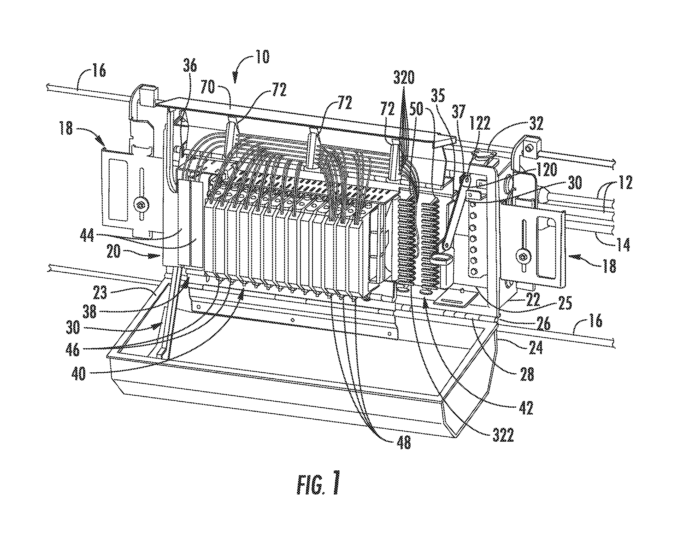
[0006]Embodiments disclosed herein include a fiber optic terminal as a local convergence point in a fiber optic network. The fiber optic terminal has an enclosure having a base and a cover which define an interior space. A feeder cable having at least one optical fiber and a distribution cable having at least one optical fiber are received into the interior space through a feeder cable port and a distribution cable port, respectively. A movable chassis positions in the interior space and is movable between a first position, a second position and third position. The movable chassis has a splitter holder area, a cassette area and a parking area. At least one cassette movably positions in the cassette area. A splitter module holder having a splitter module movably positioned therein movably positions in the splitter holder area. The optical fiber of the feeder cable and the optical fiber of the distribution cable are optically connected through the cassette. The optical connection betw...


PUM

PropertyMeasurementUnit
heightaaaaaaaaaa
widthaaaaaaaaaa
lengthaaaaaaaaaa

Abstract

A variably configurable fiber optic terminal as a local convergence point in a fiber optic network is disclosed. The fiber optic terminal has an enclosure having a base and a cover which define an interior space. A feeder cable having at least one optical fiber and a distribution cable having at least one optical fiber are received into the interior space through a feeder cable port and a distribution cable port, respectively. A movable chassis positions in the interior space and is movable between a first position, a second position and third position. The movable chassis has a splitter holder area, a cassette area and a parking area. A cassette movably positions in the cassette area. A splitter module holder having a splitter module movably positioned therein movably positions in the splitter holder area. The optical fiber of the feeder cable and the optical fiber of the distribution cable are optically connected through the cassette, which also may be through the splitter module. In such case, the optical fiber of the feeder cable optically connects to an input optical fiber to the slitter module, where the optical signal is split into a plurality of output optical fibers. One of the plurality of output optical fibers connects to the optical fiber of the distribution cable for distribution towards a subscriber premises. The interior space is variably configurable by changeably positioning the cassette and splitter modules in the movable chassis.

Description

CROSS-REFERENCE TO RELATED APPLICATIONS[0001]This application is a continuation of International Application No. PCT / US09 / 62266, filed Oct. 27, 2009, which claims the benefit of U.S. Provisional Application Ser. No. 61 / 108,788, filed Oct. 27, 2008, the contents of both of which are relied upon and incorporated herein by reference in their entireties.BACKGROUND[0002]1. Field of the Invention[0003]The present invention relates generally to fiber optic terminals, and more particularly to a fiber optic terminal which provide a local convergence point between a service provider and a subscriber in a fiber optic network that has a small form factor and is variably configurable and modular.[0004]2. Technical Background[0005]Fiber optic terminals in a fiber optic network may be referred to as local convergence points (LCP), fiber distribution terminals (FDT), fiber distribution hubs (FDH), and the like. Such fiber optic terminals are typically cabinets or enclosures which may house fiber co...

Claims


Application Information

Patent Timeline
Patent Type & Authority Patents(United States)
IPC IPC(8): G02B6/00G02B6/44
CPCG02B6/4471G02B6/4454G02B6/4452Y10T29/49826
Inventor CONNER, MARK EDWARDGIRAUD, WILLIAM JULIUS MCPHILNORED, LEE WAYNESCHNICK, GARY BRUCE
Owner CORNING OPTICAL COMM LLC
Learn More