Inductive charging method for vehicles

a charging method and inductive technology, applied in charging stations, transportation and packaging, safety/protection circuits, etc., can solve the problem of no possibility for water to enter charging sockets, and achieve the effect of reducing costs, increasing the total voltage of charging vehicles, and preventing electricity leakage and th

Active Publication Date: 2014-10-14
FU TONG TECH
View PDF14 Cites 6 Cited by
  • Summary
  • Abstract
  • Description
  • Claims
  • Application Information

AI Technical Summary

Benefits of technology

[0010]The primary object of the present invention is to enable the PS device to transmit electric power wirelessly through frequency converter PS modules and to enable series connected PR modules of the PR device to receive electric power, so as to increase the total voltage to charge vehicles. By using shunts and bleeder circuits, the PR microprocessor can receive the total output voltage that has been shunted for comparison without installing high-voltage resistant components. As it is unnecessary to make wired connections, there is no possibility for water to go into charging sockets. Besides, it can perform activities related to identification, stored value or deductions through data transmission, thus achieving the purposes of lower cost, convenience for use and preventability of electricity leakages and thefts.
[0011]A secondary purpose of the present invention is to enable PS microprocessors of first frequency converter PS sub-modules in the frequency converter PS module to perform power adjustment by frequency conversion via the coil voltage detection circuit, so as to ensure that the output power is the same as the preset power and to prevent situations of too low or high voltage from occurring. This can avoid the problems of causing the PR modules of the PR device unable to be charged or in danger following receipt of electric power, thus achieving the purposes of stable and safe charging.

Problems solved by technology

As it is unnecessary to make wired connections, there is no possibility for water to go into charging sockets.

Method used


Image

  • Inductive charging method for vehicles
  • Inductive charging method for vehicles
  • Inductive charging method for vehicles

Examples


Embodiment Construction

[0022]To achieve the aforesaid objects and functions as well as the techniques adopted in the present invention and its fabrication, examples of the preferred embodiments of the present invention are given below to illustrate features and functions of the present invention in detail by referring to the accompanying drawings.

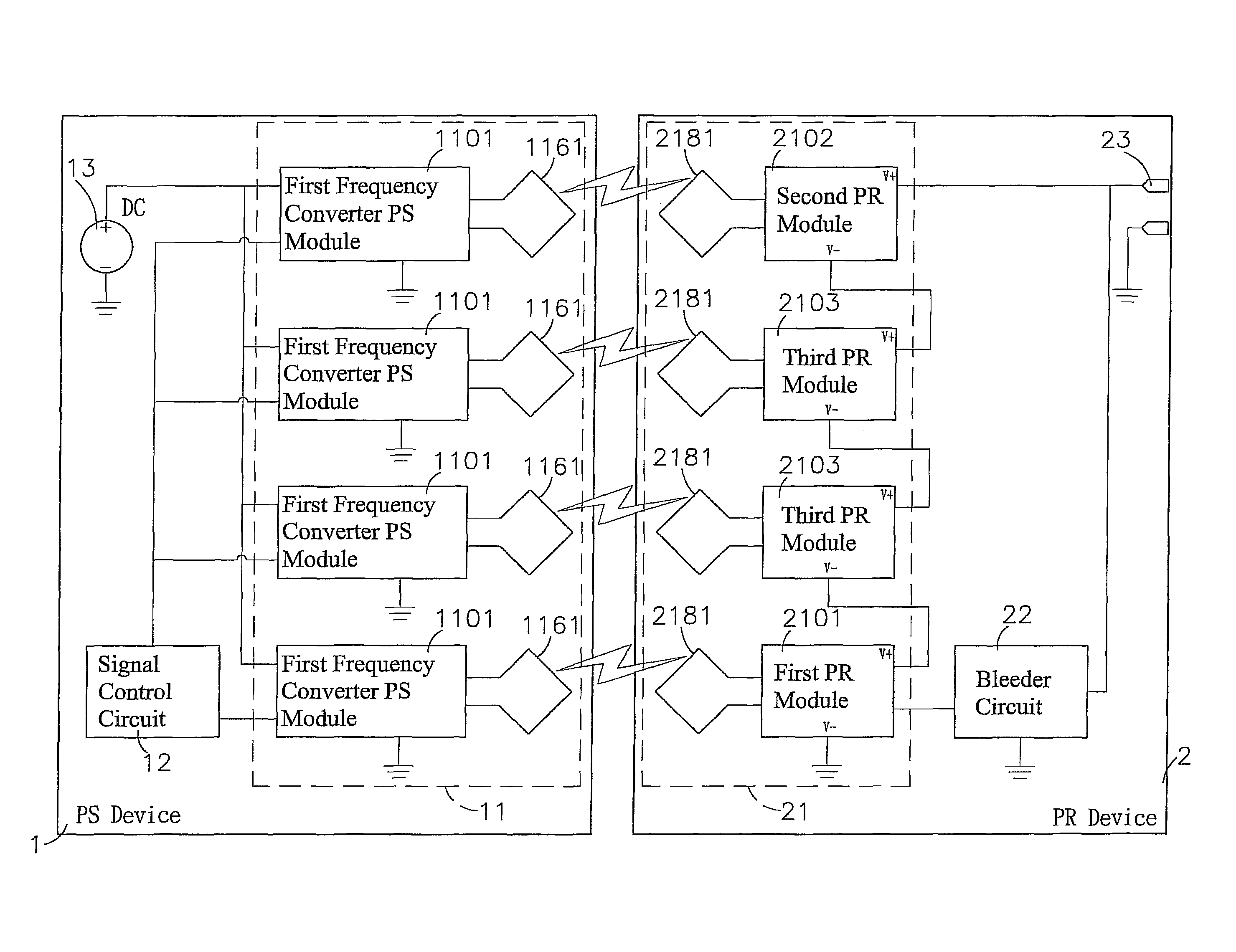
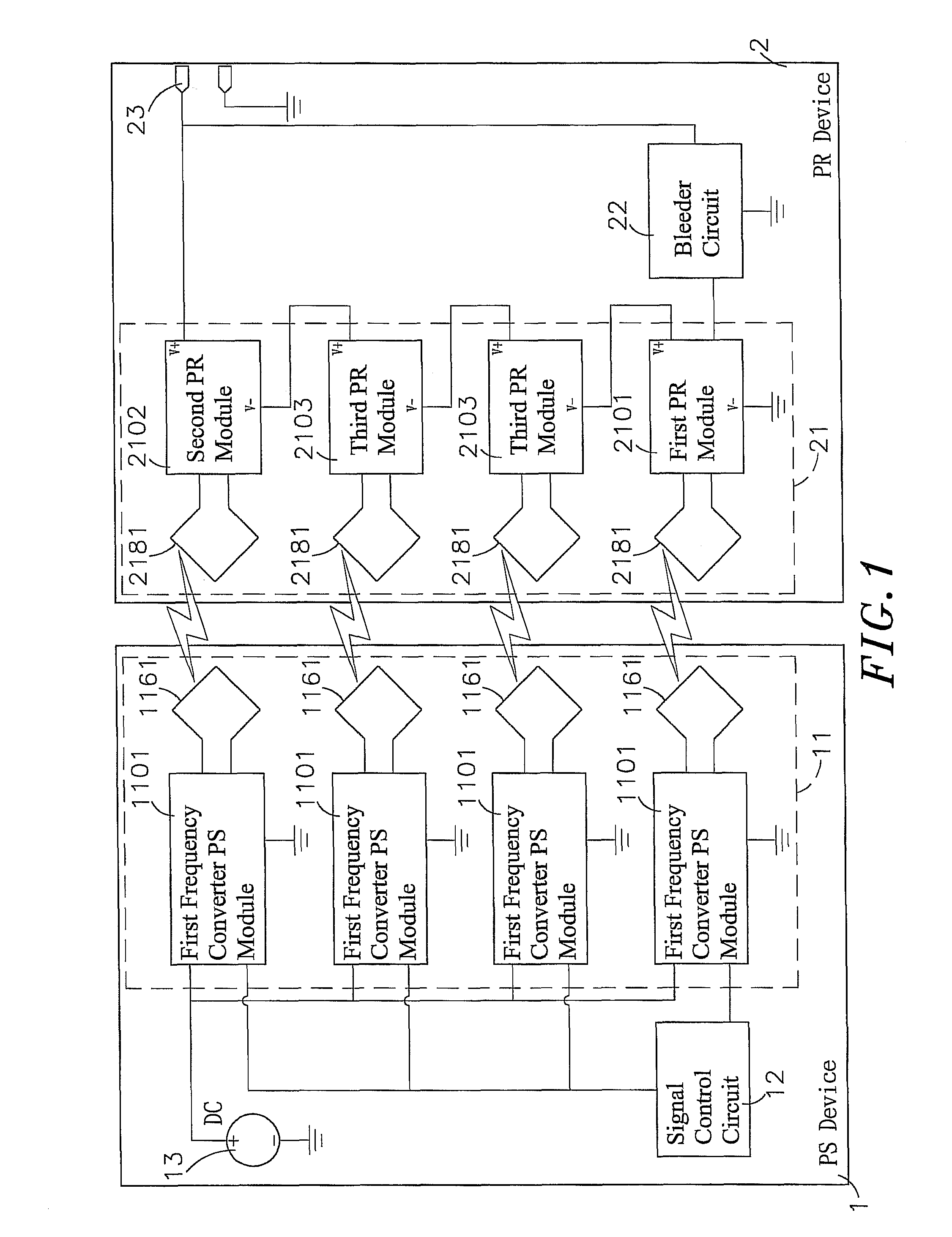
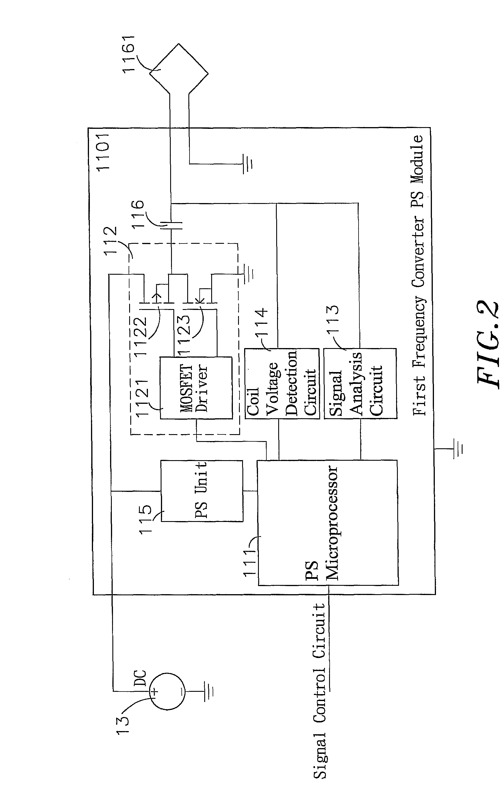
[0023]Refer to FIGS. 1, 2, 3 and 4, which are block diagrams of the circuits of the first frequency converter PS sub-module, of the first and third PR sub-modules and of the second PR sub-module according to the present invention. As shown clearly in these figures, the inductive charging method for vehicles comprises a PS device 1 and a PR device 2, wherein:

[0024]The PS device 1 includes a frequency converter PS module 11, in which two or more first frequency converter PS sub-modules 1101 are installed in parallel, and each of the first frequency converter PS sub-modules 1101 includes a PS microprocessor 111 in which the operating program, control program, data c...


PUM


Abstract

An inductive charging method for vehicles includes a power sourcing (PS) device using a first frequency converter PS sub-module to detect a power receiving (PR) device. The PS microprocessor can compare ID codes of the PR device and check power receiving status data codes. When finding an incorrect power supply, the PS microprocessor will mark it and make other first frequency converter PS sub-modules to cut off power supply through the signal control circuit, and even adjust output power based on power status data codes from the PR device. As total voltage of the PR module is increased by series connection, it is not necessary to use components of high-voltage specifications and water cannot go into sockets, thus preventing electricity leakage. Besides, no wired connection is required and operations concerning identification, stored value or deductions can be carried out.

Description

[0001]This application claims the priority benefit of Taiwan patent application number 100128812 filed on Aug. 12, 2011.BACKGROUND OF THE INVENTION[0002]1. Field of the Invention[0003]The present invention relates to an inductive charging method for vehicles, particularly to the method which utilizes a frequency converter power sourcing (PS) module in a PS device to connect with a signal control circuit and a power source and series connected power receiving (PR) modules in a PR device to connect with a bleeder circuit and a PR output terminal, allowing vehicles to be wirelessly charged and identified, make comparisons of voltages, adjust power and transmit data, thus achieving the effect of convenience in use and prevention of electricity leakage and theft.[0004]2. Description of the Related Art[0005]Generally, most of electric vehicles are equipped with storage batteries inside. Such vehicles need to be charged when electricity in the storage batteries run out or is insufficient t...

Claims


Application Information

Patent Timeline
Patent Type & Authority Patents(United States)
IPC IPC(8): H02J7/00B60L11/18H02J5/00H02J7/02
CPCH02J5/005H02J7/025B60L11/1846B60L11/182Y02T90/122Y02T90/128Y04S30/14Y02T10/7088Y02T10/7005Y02T90/163Y02T90/169Y02T90/14Y02T90/121B60L11/1812Y02T10/7072B60L53/22B60L53/12B60L53/65H02J7/007182H02J7/00304Y02T10/70Y02T90/12Y02T90/167H02J50/80H02J50/90H02J50/12H02J50/70Y02T90/16
Inventor CHAN, CHI-CHETSAI, MING-CHIU
Owner FU TONG TECH
Why Eureka
Try Eureka