
Friction piece in a lubricated medium, working at contact pressures higher than 200 MPa

a friction piece and lubricating medium technology, applied in the field of friction pieces in lubricated medium, can solve the problems of oil film pressure drop, surface damage, and possible embrittlement of layers and flaking,

Active Publication Date: 2014-10-14
H E F +3
View PDF12 Cites 5 Cited by
  • Summary
  • Abstract
  • Description
  • Claims
  • Application Information

AI Technical Summary

Benefits of technology

The patent describes a method for improving the lubrication performance of friction parts by texturing their surface and applying a case hardening treatment using a thin layer of amorphous carbon (DLC) to reduce friction and protect the surfaces from wear and damage. The depth of the cavities in the textured surface should be minimized to optimize the influence of the lubrication regime. The addition of a hard layer after texturizing further reduces damage and maintains the textured surface's performance.

Problems solved by technology

Above this thickness, risks of embrittlement of the layer and flaking may occur.
However, the dimensioning of the surface topography is not a simple matter, so that this solution is incompatible with severe contact conditions, and also in the case of heavily loaded friction parts, that is, where the contact pressures give rise to operation in conditions called elastohydrodynamic regime.
In fact, this texturizing, which is equivalent to etching patterns on the contact surface, causes a significant decrease in the bearing surface area, so that an unsuitable texturizing inevitably causes a drop in pressure of the oil film and damage to the surfaces, which militates against the desired objective.

Method used


Image

  • Friction piece in a lubricated medium, working at contact pressures higher than 200 MPa
  • Friction piece in a lubricated medium, working at contact pressures higher than 200 MPa
  • Friction piece in a lubricated medium, working at contact pressures higher than 200 MPa

Examples


Embodiment Construction

[0031]Reference can be made to example No. 1 of the treatment below:

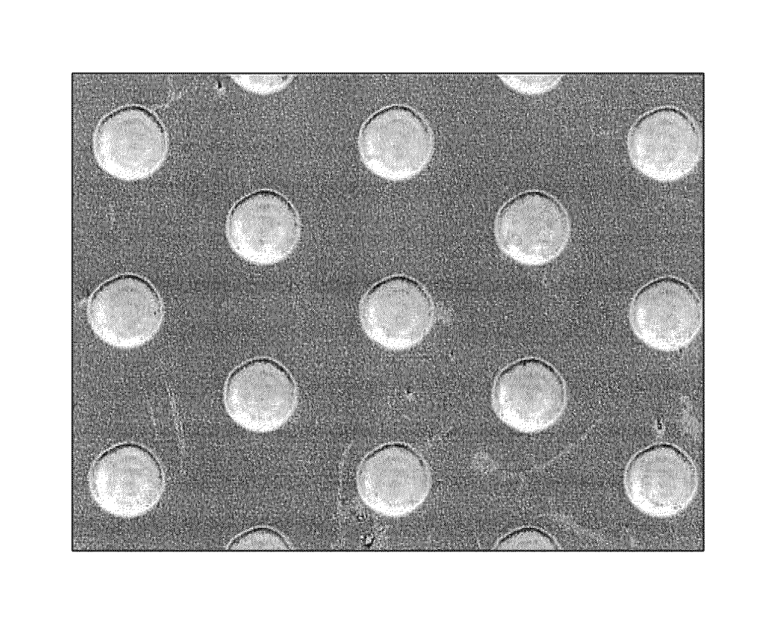
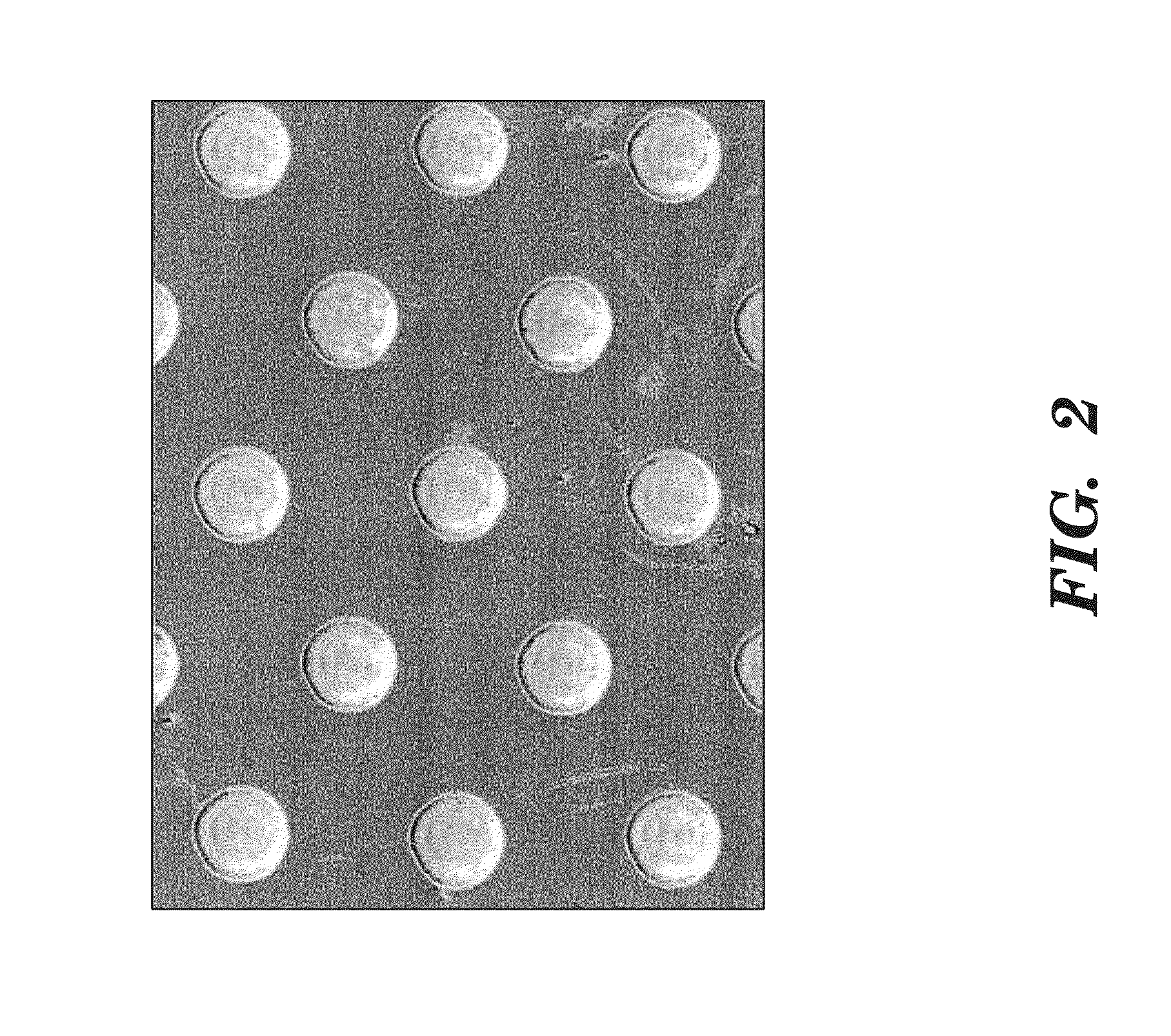
[0032]The parts treated are rollers with a spherical bearing surface 50 mm in diameter, made from tribofinished X85WCrMoV6-5-4-2 steel. These parts have been coated with a 2 μm thick DLC deposit, in which holes (circular microcavities) have been prepared by femtosecond laser pulses. The surfaces are textured by a network of holes 79 μm in diameter and 400 nm deep, with a spacing of 125 μm, as shown in FIG. 2. The network consists of a succession of rows of 7 and 8 offset holes, on a 1 mm wide strip placed at the centre of the roller friction track.

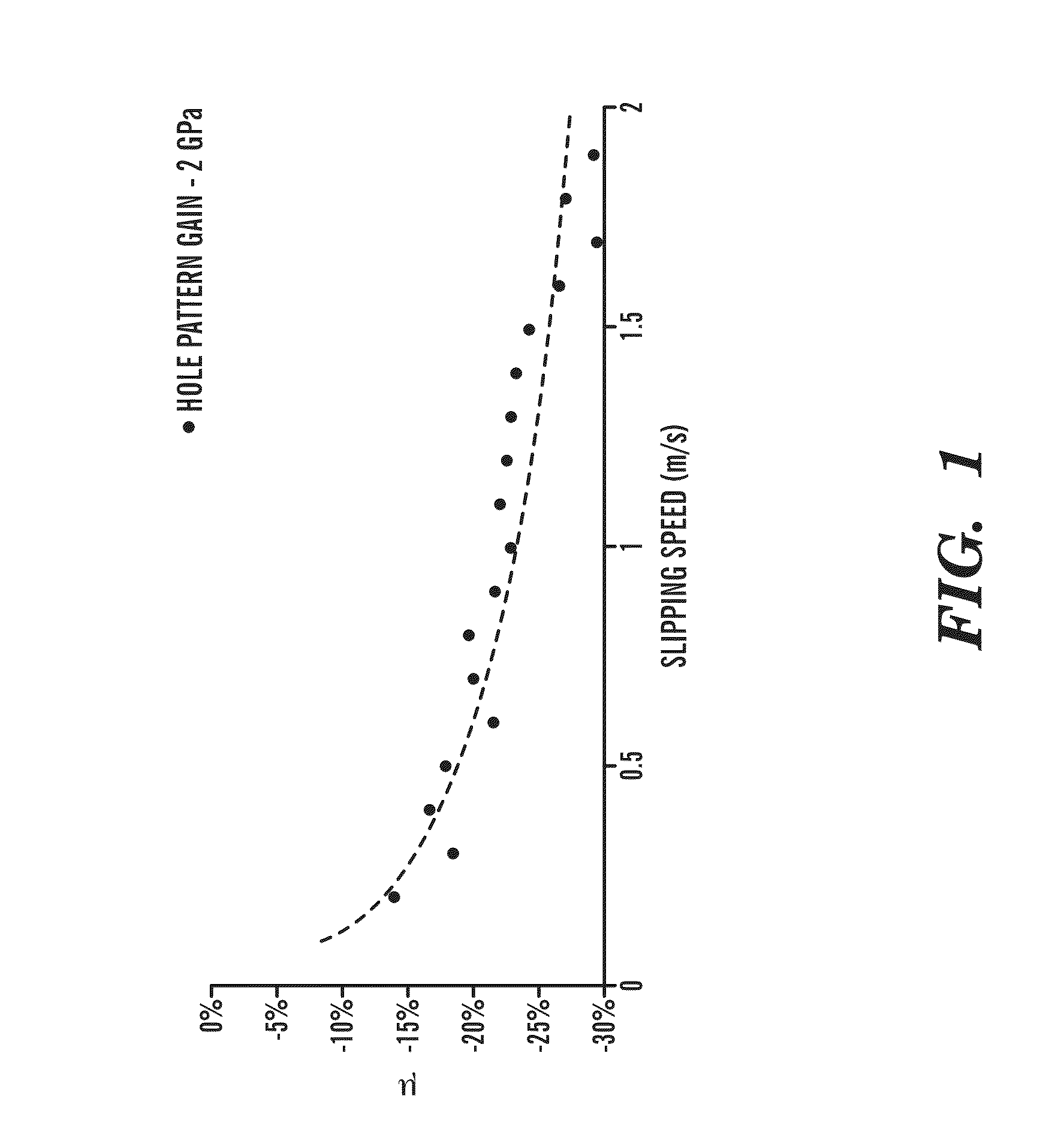
[0033]These rollers are used for friction tests on a “Amsler” machine (reference tribological test for a person skilled in the art), under high contact pressures (1 to 3.2 GPa maximum contact pressure), sliding speeds from 0.2 to 2 m / s, and low lubricant entrainment speeds in the contact (10% of the sliding speed). Each textured part has been tested opposite an uncoated an...


PUM

PropertyMeasurementUnit
thicknessaaaaaaaaaa
lengthaaaaaaaaaa
lengthaaaaaaaaaa

Abstract

Friction part in a lubricated medium working at contact pressures above 200 MPa and having a contact surface that is textured and subjected, before or after texturizing, to a case hardening treatment for a tribological function, wherein the surface is subjected to operations for producing a periodic network of micrometric cavities having predefined shapes and sizes and a period adapted to the width of the contact surface in order to promote passage to elastohydrodynamic lubrication regime.

Description

CROSS REFERENCE TO RELATED APPLICATIONS[0001]This application is a national stage filing under section 371 of International Application No. PCT / FR2007 / 052204 filed on Oct. 19, 2007, and published in French on Apr. 24, 2008 as WO 2008 / 047062 and claims priority of French application No. 0654414 filed on Oct. 20, 2006, the entire disclosure of these applications being hereby incorporated herein by reference.BACKGROUND ART[0002]The invention relates to the technical field of tribology in lubricated medium.[0003]More particularly, the invention relates to coatings and surface treatments designed to reduce wear and to minimize the transmission of tangential forces.[0004]Numerous technical solutions have been proposed for improving the tribological performance of mechanical parts. A distinction is made essentially between conventional case hardening treatments and deposits of thin and hard layers obtained by various methods such as PVD (Physical Vapour Deposition) or PACVD (Plasma Assiste...

Claims


Application Information

Patent Timeline
Patent Type & Authority Patents(United States)
IPC IPC(8): B32B3/12B23K26/00B23K26/06C23C14/06C23C14/58F01L1/16F01L1/18F16C33/10F16C33/14F16H53/06F16H55/06
CPCB23K26/0084C23C14/5873C23C14/0605B23K26/0635F16H55/06F16H53/06F16C2240/40F16C33/14F01L2820/01F16C33/103F01L1/16F01L1/18Y10T74/19Y10T74/2107Y10T428/24355B23K26/0624F16C2223/60F16C2223/16F16C2220/40F16C2240/44B23K26/355B23K26/0622C23C14/06F16C33/10
Inventor MAURIN-PERRIER, PHILIPPELEDRAPPIER, FLORENTMOURIER, LOUISDONNET, CHRISTOPHEAUDOUARD, ERICMAZUYER, DENIS
Owner H E F
Learn More