Hog confinement building ventilation system

a ventilation system and confinement building technology, applied in ventilation systems, lighting and heating apparatus, heating types, etc., can solve the problems of noxious gases and fumes rising upwards, killing pigs, and high flammability of methane, so as to minimize air turbulence adjacent to the confinement building slatted floor

Active Publication Date: 2014-10-14
KLOCKE DAVE
View PDF41 Cites 1 Cited by
  • Summary
  • Abstract
  • Description
  • Claims
  • Application Information

AI Technical Summary

Benefits of technology

[0016]In both embodiments, air turbulence adjacent the slatted floor of the confinement building is minimized, since the expelled air is pulled from a distance spaced downwardly from the slatted floor adjacent the manure surface. Thus, a rise of noxious gases from the manure pit through the slatted floor is eliminated or minimized.

Problems solved by technology

Methane is highly flammable.
During pit pumping, agitation of the waste material releases hydrogen sulfide, which may kill the pigs if concentration levels rise too high.
However, these fans typically pull air from an area immediately below the slatted floor of the building which may create turbulence and cause noxious gases and fumes to rise upwardly through the slatted floor, which is unhealthy and potentially deadly to the pigs in the confinement building.
Also, pumping sometimes creates pit foaming, which causes methane bubbles to be released, which further contaminates the building air.
Some farmers tend to over ventilate their barns.
In the winter, excess air removal and replacement with fresh outside air requires more heating, which necessarily requires more costs to the farmer.
In the summer, excess air removal and replacement with fresh, hot outside air requires more cooling, and thus more costs to the farmer.

Method used


Image

  • Hog confinement building ventilation system
  • Hog confinement building ventilation system
  • Hog confinement building ventilation system

Examples


Embodiment Construction

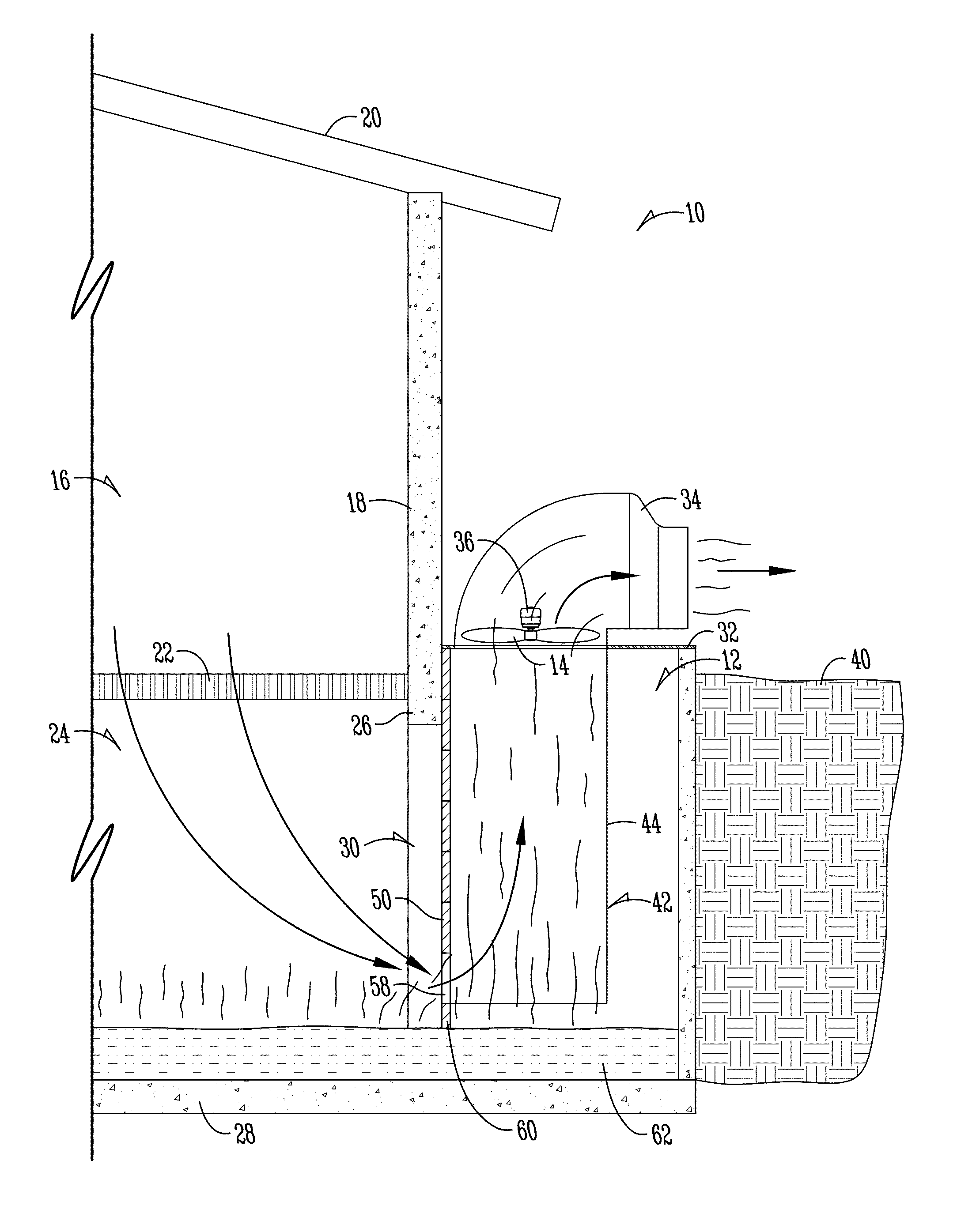
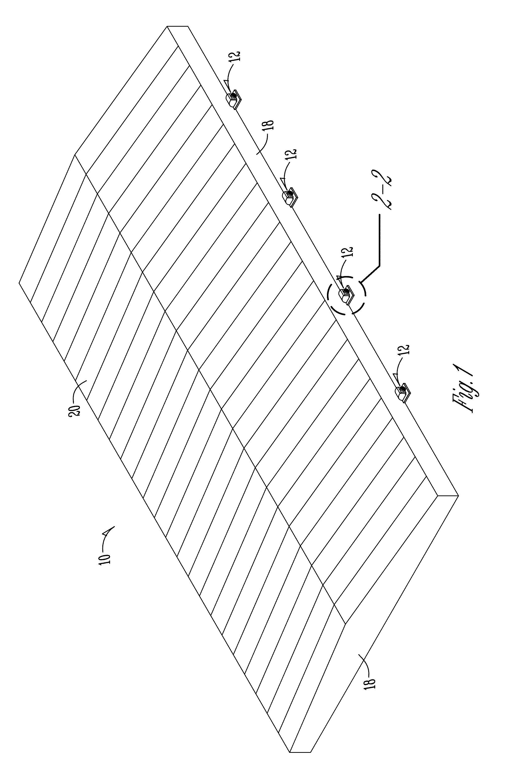
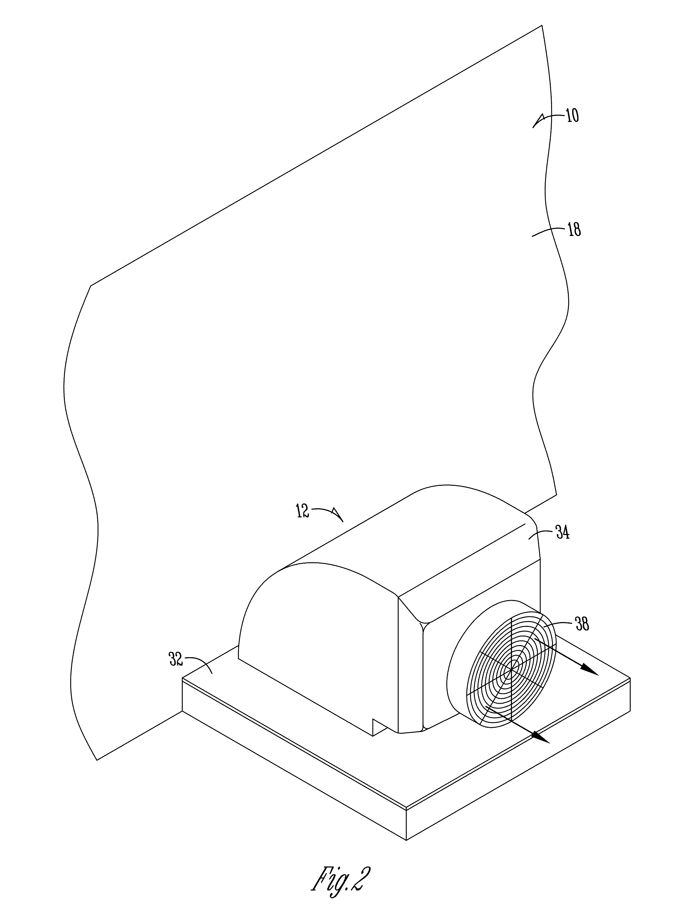
[0027]FIG. 1 shows the basic structure of a hog confinement building 10 having a series of pump out pits 12 spaced along opposite sides of the building 10. A fan 14 is mounted on the top of each pump out pit 12 as best seen in FIG. 2. As shown in FIGS. 3 and 4, the building 10 includes a hog confinement area 16 defined by perimeter walls 18, a roof 20, and a slatted floor 22. A waste material or manure pit or reservoir 24 is provided beneath the slatted floor 22, as defined by the foundation walls 26 and the reservoir floor 28. Each pump out pit 12 is formed adjacent the foundation walls 26, with an opening 30 being formed in the foundation wall 26 to provide flow of waste material from the manure reservoir 24 into the pump out pit 12. As seen in FIGS. 2-4, a cover 32 is provided on the top of each pit 12. A fan housing 34 is mounted on each cover 32 and encloses the fan 14 and fan motor 36. The housing 34 includes an exhaust opening covered by a grate or screen 38. Thus, as seen in...


PUM


Abstract

A ventilation system is provided for a hog confinement building having a slatted floor, a manure reservoir beneath the floor, and a pump out pit in communication with the reservoir. The ventilation system includes a fan on top of the pump out pit, with an air conduit extending downwardly from the fan. A gate is slidably mounted on the conduit, with a float on the bottom end of the gate. The float sits on the surface of the manure, such that the gate rises and falls with changes in the manure level. A ventilation opening on the lower end of the gate allows air to be drawn from the manure reservoir adjacent the surface of the manure, upwardly through the conduit for expulsion by the fan. Air turbulence beneath the slatted floor is minimized to reduce or eliminate rising noxious gases through the slatted floor.

Description

FIELD OF THE INVENTION[0001]The present invention generally relates to hog confinement buildings, and particularly to an improved ventilation system which provides an enhanced air quality within the building. The present invention pulls air from the manure pit at a level adjacent the surface of the manure so as to eliminate or minimize air turbulence and return of noxious gases from the manure pit through the slatted floor to the hog confinement area.BACKGROUND OF THE INVENTION[0002]Hog confinement buildings typically house hundreds of animals which produce a substantial volume of urine and manure waste. The urine and manure waste material in the reservoir produces noxious gases, including hydrogen sulfide, ammonia, and methane. Methane is highly flammable. The buildings normally have a slatted floor through which these waste materials fall into a pit or reservoir, and must periodically be removed before the pit fills to capacity. Some hog confinement buildings include pump out pits...

Claims


Application Information

Patent Timeline
Patent Type & Authority Patents(United States)
IPC IPC(8): A01K1/00
CPCF24F7/065A01K1/0052A01K1/0151F24F2007/001A01K1/0047
Inventor KLOCKE, DAVE
Owner KLOCKE DAVE
Why Eureka
Try Eureka