Tube Connector for Intake Manifold

a technology for intake manifolds and conduits, which is applied in the direction of hose connections, pipe joints, and fluid pressure sealing joints, etc., can solve the problems of affecting the efficiency of the engine, and the engagement of the clamp and hose is generally unsightly, so as to achieve the effect of reducing air turbulen

Inactive Publication Date: 2010-01-28
RICHARDS TIMOTHY J
View PDF18 Cites 2 Cited by
  • Summary
  • Abstract
  • Description
  • Claims
  • Application Information

AI Technical Summary

Benefits of technology

[0013]The disclosed device provides great utility in solving the aforementioned problems related to intake air and fluid conduit connectors for internal combustion engines such as the conduit leading from the air cleaner to the air intake for the fuel injection or similar air and fuel mixing system of the vehicle. The device is especially well adapted to racing and high performance applications where a quickly engageable connector, which is secure from vibration, yet minimizes air turbulence in the formed conduit, would be a competitive performance advantage.

Problems solved by technology

The use of a clamp and hose engagement is generally unsightly, creates a need for a hose clamp removal tool, and is subject to leaks as it ages.
Further conventional flexible conduits create turbulence inside the conduit from the uneven surfaces of the inside surfaces of the hose and the aluminum, metal, or plastic conduits providing the measured clean air supply to the throttle valve intake.
It is well known that such air turbulence caused by the uneven surfaces inhibits the efficiency of the engine.
However, such devices are expensive and fail to form a smooth interior wall of the joined components.
Further, such are known to suffer from a loosening of the threadably engaged components caused by engine vibration communicated through the solid component parts from the engine.
This loosening effect can occur rapidly unless secured with an unsightly clamp or other locking device to prevent the loosening over time of the connection threaded connections.
However, detachment is inhibited in that it requires one or two wrenches to disengage the components and provides for a slow removal.
Air leaking into the conduits after a volume has been measured and communicated to a fuel calculating component will cause a mismatch of the calculated fuel and air ratio fed to the engine.
Such leaking can cause an unsafe or inefficient air to fuel ratio since the connection of the conduit components is generally located past the air flow sensor delivering air intake volume to the engine's computer which employs such to regulate fuel flow to match air intake volume.
Any such extra air communicated into the system at the point of the connection, if past the air volume measurement point, will generally cause a lean mixture in the engine.
Lean mixtures are known to cause pre-ignition which, unchecked, can damage the engine.
However, such connections must be secure, air tight, resistant of vibration, and permit little or no formation of air turbulence inside the conduits which could rob performance.

Method used


Image

  • Tube Connector for Intake Manifold
  • Tube Connector for Intake Manifold
  • Tube Connector for Intake Manifold

Examples


Embodiment Construction

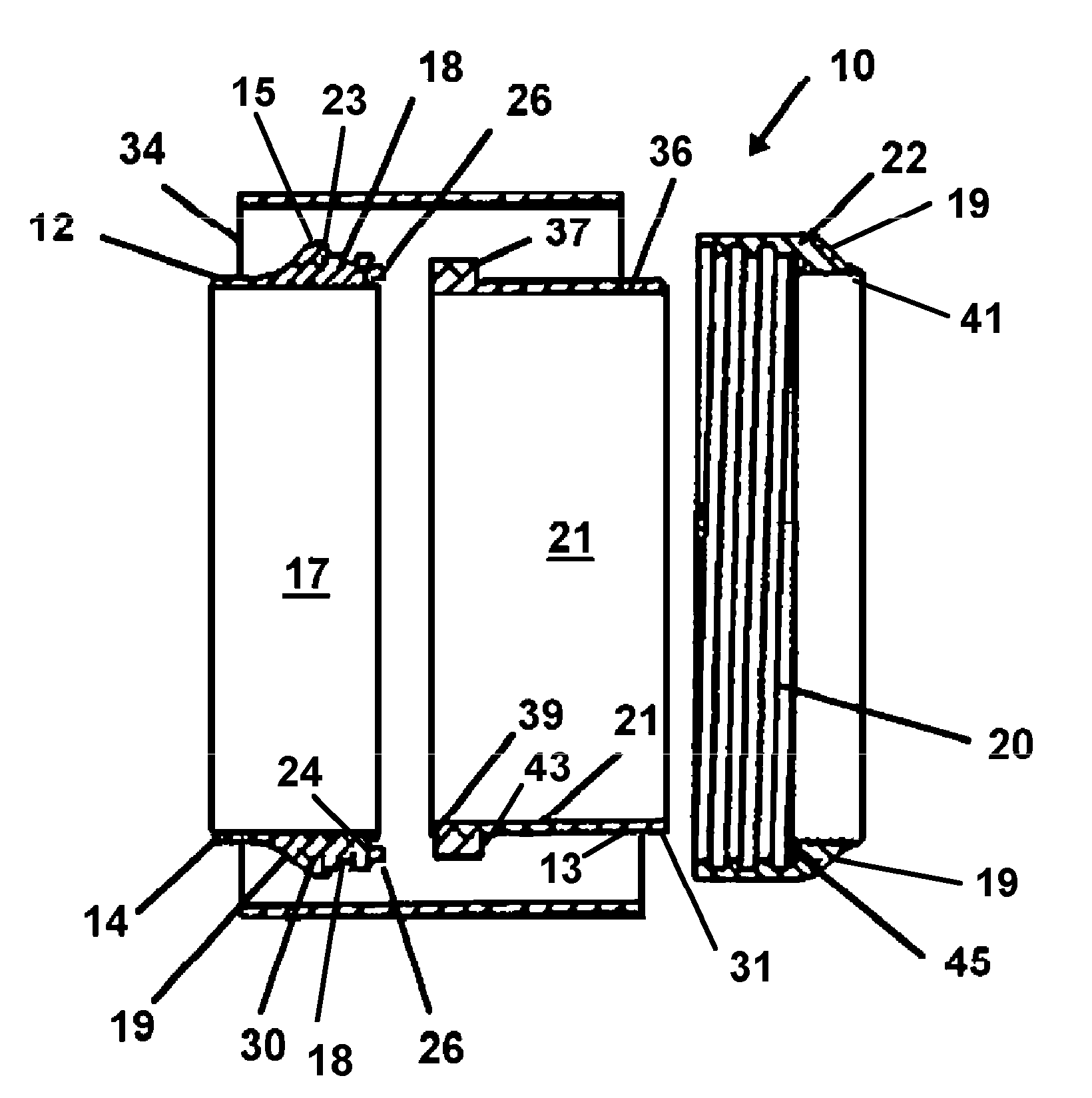
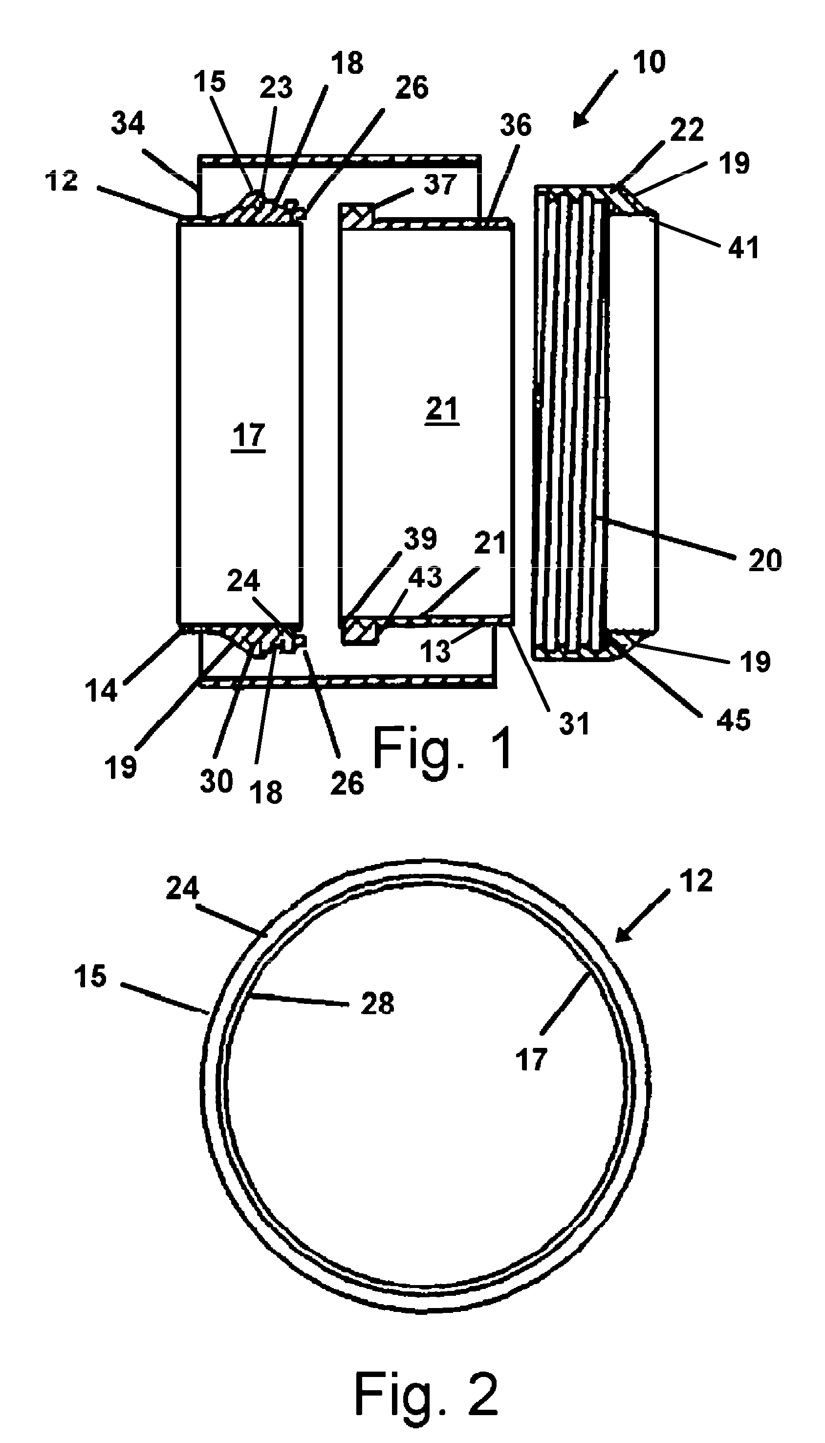
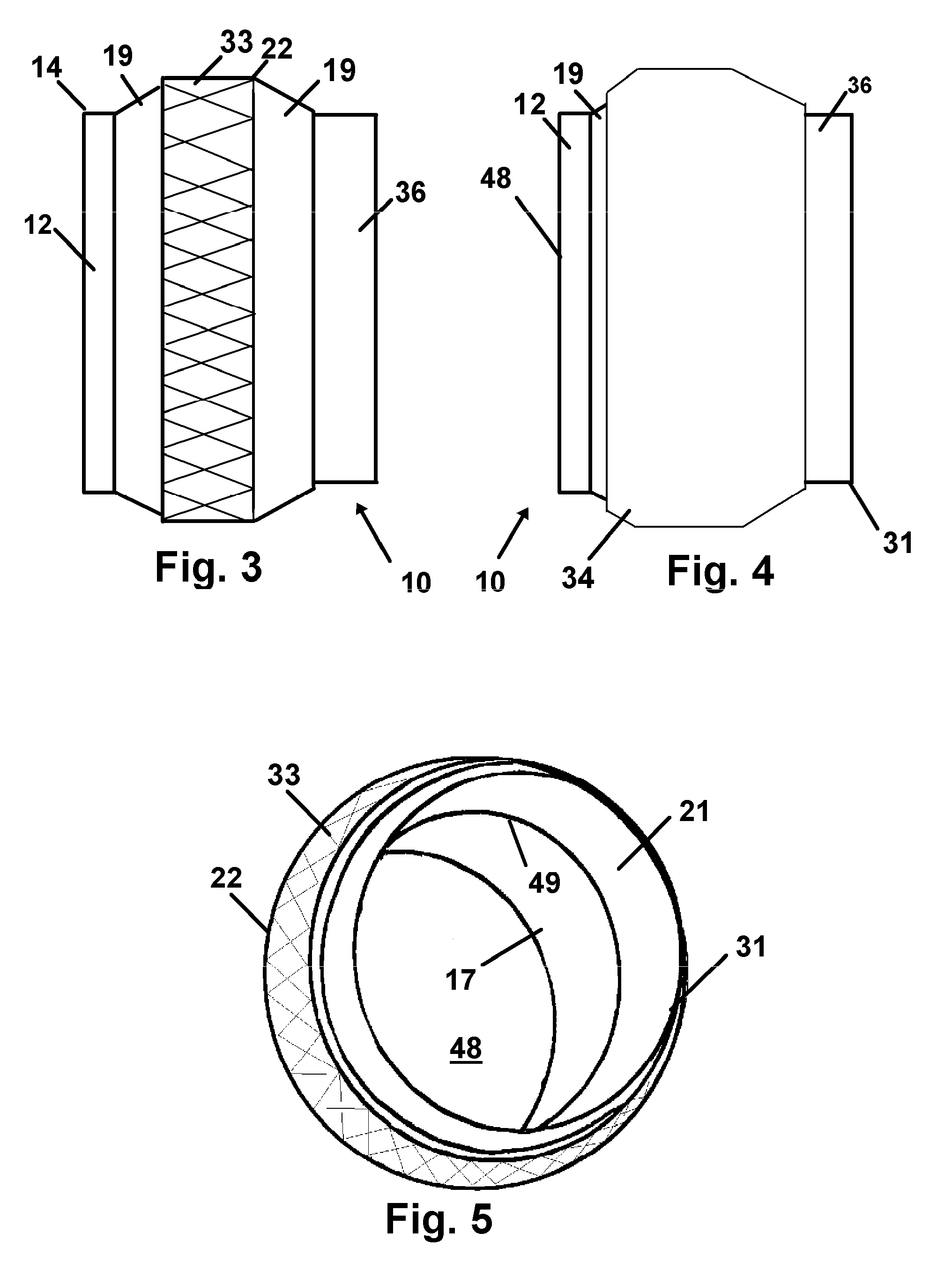
[0032]The device 10 herein is described and disclosed in FIGS. 1-5 wherein similar parts are identified by like reference numerals, which may be found in one or more of the drawings.

[0033]As depicted in FIG. 1 in a sliced view through the exploded components aligned along an axis, the device 10 features a first connector 12 adapted at a first end 14 for engagement to the air intake conduit of an internal combustion engine modernly leading to a throttle body. On the exterior surface 15 of the first connector 12 at a second end opposite the first end 14, threads 18 are formed sized to engaged mating threads 20 formed on the interior surface of the ring component 22.

[0034]A mating surface 24 communicating on a side between the exterior surface 15 and the interior surface 17 has a resilient “O” ring 26 as a sealing means engaged thereon. Means for engagement of the O-ring 26 to the mating surface 24 in the current preferred mode of the device 10 is provided by an annular slot 28 shown i...


PUM


Abstract

An air intake conduit connecter having two components engaged by an annular ring engaging one component and biasing towards the engagement. A resilient band is engageable around the annular ring to allow hand tightening thereof and preventing vibration from loosening the threaded engagement of the ring.

Description

FIELD OF THE INVENTION[0001]The disclosed device relates to connections for fluid conduits. More particularly it relates to a conduit connection for an intake manifold for an internal combustion engine which allows for the quick engagement and disengagement of the connection while concurrently providing a sealed communication between the two adjoining component conduits. In addition to a frictional engagement of components by a threaded collar, an elastic safety band wider than the collar, provides a means to prevent the connection from loosening due to engine vibration.BACKGROUND OF THE INVENTION[0002]Modern internal combustion engines must have a regulated supply of air to mix with a measured amount of fuel being provided for combustion in the cylinders. A conventional design for delivering air for mixture with the fuel employs a throttle body which is opened and closed to allow varied amounts of air for mixture with fuel communicated to the engine combustion system. On a fuel-inj...

Claims


Application Information

Patent Timeline
Patent Type & Authority Applications(United States)
IPC IPC(8): F16L17/00
CPCF16L19/005
Inventor RICHARDS, TIMOTHY J.
Owner RICHARDS TIMOTHY J
Why Eureka
Try Eureka