
Collapsible lantern

a lantern and collapsible technology, applied in the field of lanterns, can solve the problems of not being suitable for a person to use a lantern, not being suitable for a person to use a spot light to provide illumination, and the inability to manufacture the final selling price of the present invention to be optimally minimized

Inactive Publication Date: 2014-10-07
LAU FERMI CHI HUNG
View PDF8 Cites 3 Cited by
  • Summary
  • Abstract
  • Description
  • Claims
  • Application Information

AI Technical Summary

Benefits of technology

The present invention is a collapsible lantern that can work in two different modes, providing different types of illumination. It can change its size and is easy to manufacture and sell. In one mode, it acts as a spot light, and in the other mode, it acts as a lantern. The lantern has a tubular lens body that can move between a collapsed position and a lantern position. The invention's features include simple mechanical and electrical structures, resulting in low manufacturing costs and minimal selling prices.

Problems solved by technology

However, the intensity of the illumination of lanterns is usually substantially smaller than traditional spot lights.
Thus, it is not suitable for a person to use a lantern to illuminate a particular spot.
On the other hand, it is also not suitable for a person to use a spot light to provide illumination for a relatively larger area of space, because conventional spot lights are designed to provide illumination of high intensity at a desirable spot.
However, one major disadvantage of this type of lamp is that it is very bulky in size, because it typically comprises a fluorescent lamp and a high-intensity LED or light bulk mounted at different positions of a housing.
Since the housing must accommodate two different kinds of light source, the size of the housing is very bulky.
This disadvantage substantially impairs widespread application of this type of lamp.

Method used


Image

  • Collapsible lantern
  • Collapsible lantern
  • Collapsible lantern

Examples


Embodiment Construction

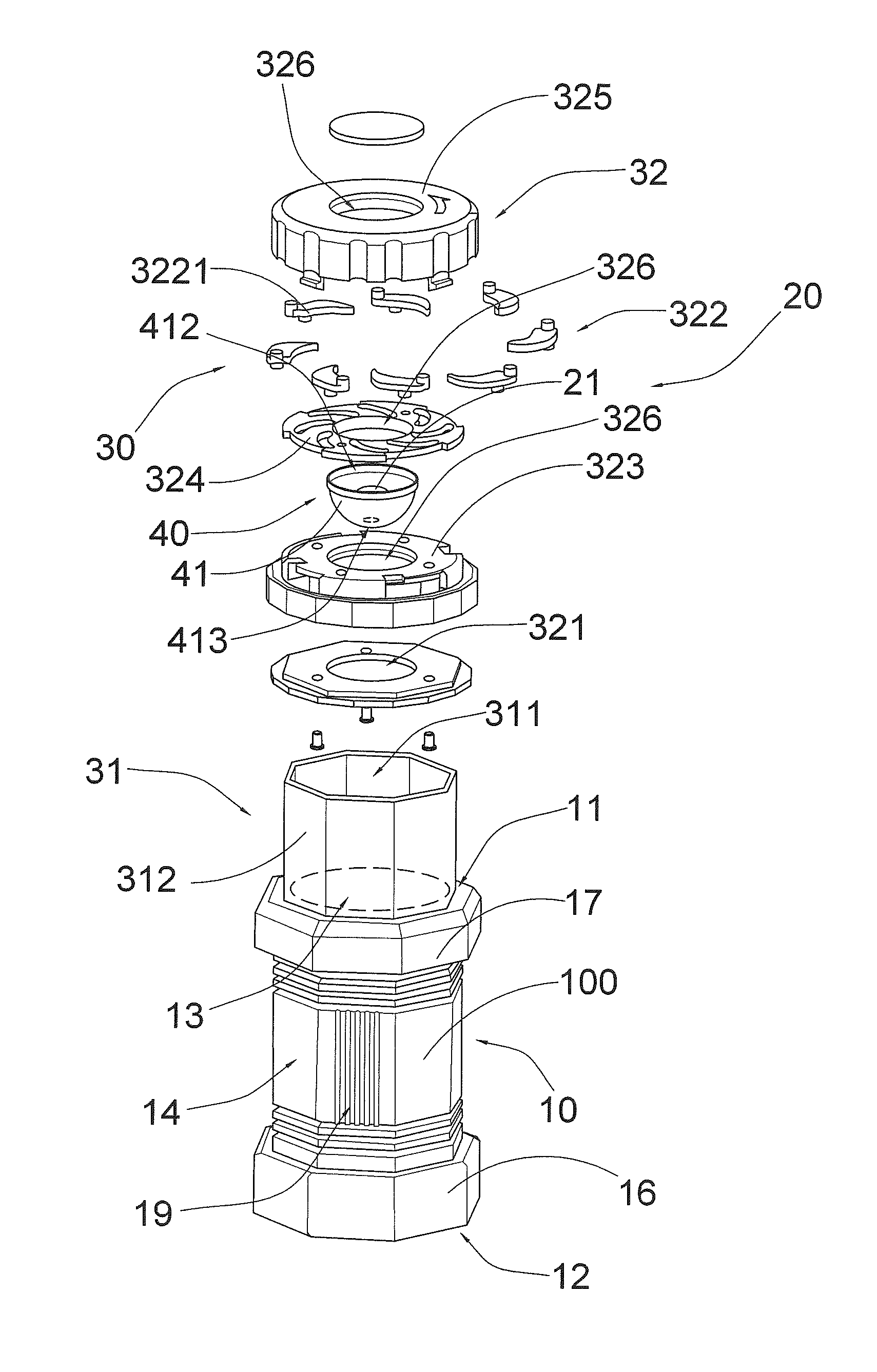
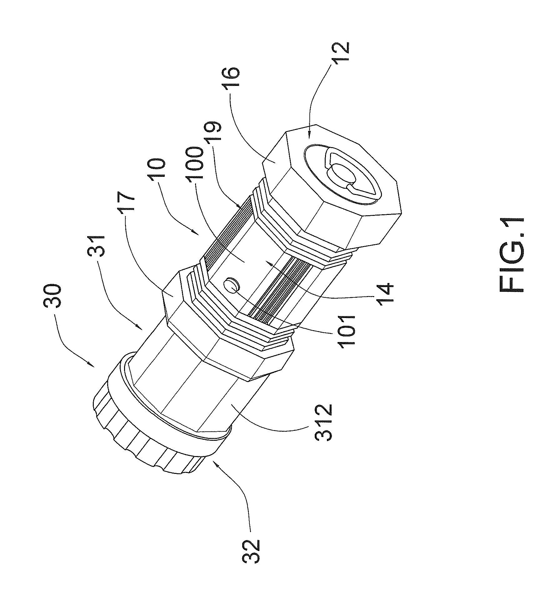
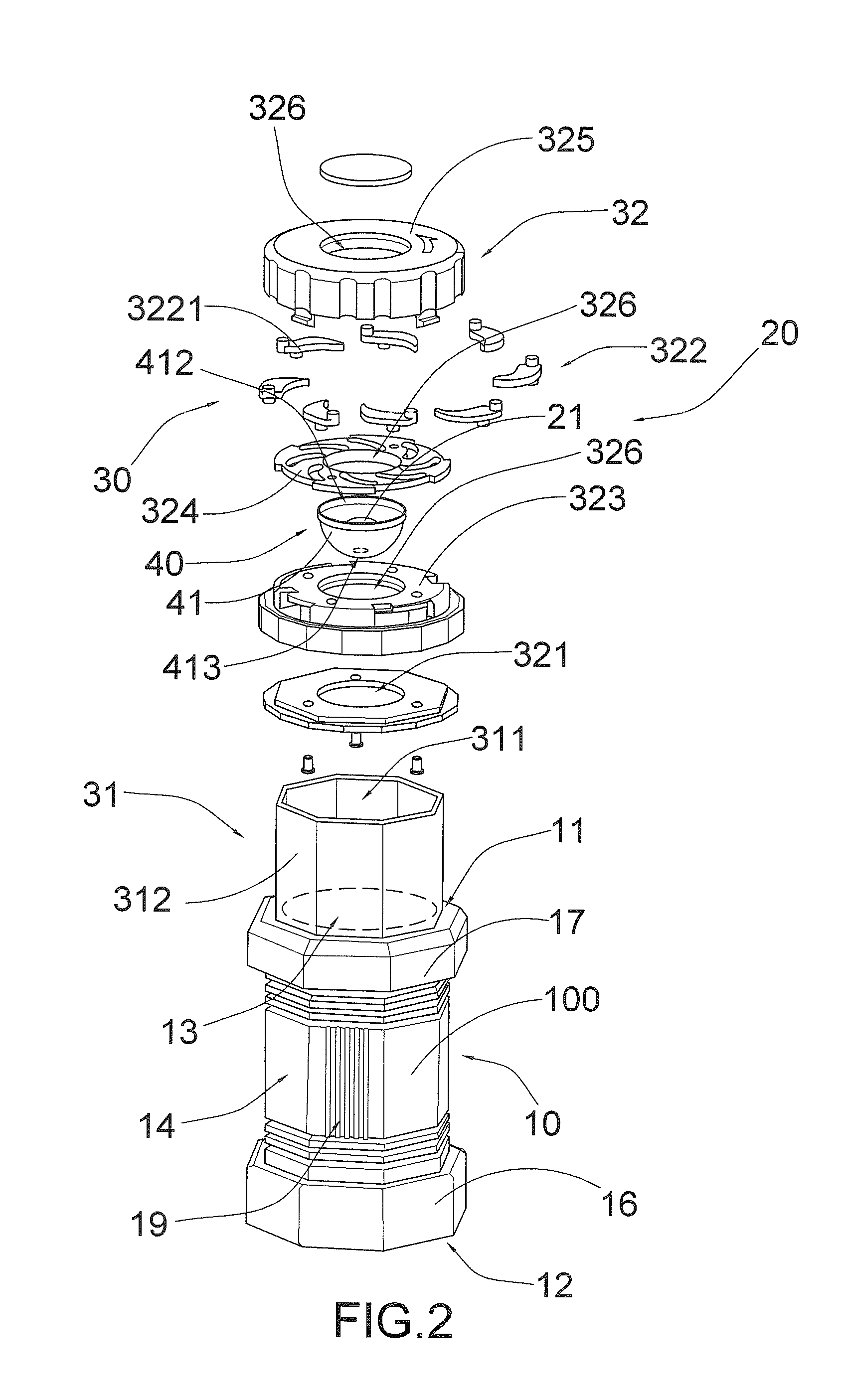
[0025]Referring 1 to FIG. 3, and FIG. 4A to FIG. 4C of the drawings, a collapsible lantern according to a preferred embodiment of the present invention is illustrated, in which the collapsible lantern comprises a lantern housing 10, an illumination unit 20, and a collapsible arrangement 30.

[0026]The lantern housing 10 has a front side 11 and a rear side 12 and a receiving cavity 13 defined between the front side 11 and the rear side 12, wherein the illumination unit 20 provided in the receiving cavity 13 of the lantern housing 10 for generating illumination.

[0027]The collapsible arrangement 30 comprises a tubular lens body 31 and a light controlling cap assembly 32. The tubular lens body has a light cavity 311 and a light admissible sidewall 312, and is movably extended from the front side 11 of the lantern housing 10 to move between a collapsed position and a lantern position.

[0028]On the other hand, the light controlling cap assembly 32 has a light window 321 provided at a front e...


PUM


Abstract

A collapsible lantern includes a lantern housing, an illumination unit and a collapsible arrangement. The latter includes a tubular lens body and a light controlling cap assembly. The tubular lens body is movably extended from the front side of the lantern housing to move between a collapsed position and a lantern position. The light controlling cap assembly has a light window and includes a light shelter, in such a manner that when the tubular lens body is at the collapsed position, the tubular lens body is moved into the lantern housing while the light shelter is driven to open the light window for allowing illumination to reach an exterior of the lantern housing. When the tubular lens body is at the lantern position, the tubular lens body is moved out of the lantern housing while the light shelter is driven to close the light window.

Description

BACKGROUND OF THE PRESENT INVENTION[0001]1. Field of Invention[0002]The present invention relates to a lantern, and more particularly to a collapsible lantern comprising a collapsible arrangement which is capable of allowing the lantern to conveniently work between two different modes of operation.[0003]2. Description of Related Arts[0004]A conventional illumination device, such as a spot light, usually comprises a housing and an illumination device provided in the housing for selectively generating illumination toward a particular spot. The user may manual hold the spot light and point it towards a desirable position. Conventionally, spot lights such as those described above usually generate illumination from a single point source of light. This kind of illumination pattern is highly beneficial when the user needs to illuminate a particular spot in larger space.[0005]On the other hand, a conventional lantern usually comprises a housing and an illumination device mounted in the hous...

Claims


Application Information

Patent Timeline
Patent Type & Authority Patents(United States)
IPC IPC(8): F21L19/00F21S8/00F21L4/00F21V17/02
CPCF21L4/005F21V7/04F21V13/02F21S9/02F21V7/0075F21V13/04F21V11/10
Inventor LAU, FERMI, CHI, HUNG
Owner LAU FERMI CHI HUNG
Learn More