Vehicle suspension system

a suspension system and vehicle technology, applied in the direction of steering linkages, endless track vehicles, transportation and packaging, etc., can solve the problems of compromising geometry, affecting the design, utility, economy and safety of vehicles, and reducing so as to achieve the effect of minimizing the impact on the interior space of vehicles

Inactive Publication Date: 2014-09-23
EDISON2
View PDF19 Cites 0 Cited by
  • Summary
  • Abstract
  • Description
  • Claims
  • Application Information

AI Technical Summary

Benefits of technology

[0014]A primary object of this invention is to permit the most desirable geometric characteristics of a suspension to be packaged more tightly than in any other suspension design.
[0016]A further object of this invention is to allow other desirable but previously difficult to achieve vehicle design characteristics such as light weight and more ideal streamlining to be incorporated into the vehicle.
[0017]Yet another object of this invention is to offer the possibility of improved vehicle crash safety.
[0018]An additional object of this invention is to retain the ability to drive the steering wheels in either a front wheel drive or four wheel drive mode while still retaining the other advantages provided by the disclosed suspension system.
[0021]Yet an additional object of this invention is to minimize impingement on vehicle interior space resulting from the suspension system.

Problems solved by technology

Known conventional suspension systems often suffer from one or more problems that individually and / or collectively restrict the design, utility, economy and safety of the vehicles in which they are used.
This design is used most in very high performance / value cars but a combination of its relative complexity (and therefore high cost) and space requirements prevent higher utilization in ordinary passenger vehicles.
While such combining of purpose and function is desirable for economy of manufacture, they are accompanied by the disadvantages of compromised geometry and the imposition of side loads on the damper.
Beam axles are cheap to manufacture but have numerous disadvantages including not allowing independent wheel motion, high unsprung weight and, because the whole axle moves with suspension travel, they take up a lot of room.
Disadvantages include the absence of camber compensation for roll, difficulty of arranging bump-steer free steering and large size.
Disadvantages include its necessarily short length causing awkwardly large camber change with the attendant gyroscopic action and its proclivity for undesirable jacking effects.
Therefore, it is clear that a fundamental problem in designing any automotive suspension system is counterbalancing conflicting requirements such as cost, weight, packaging constraints and geometric characteristics.
In addition, where and how a vehicle's suspension is mounted has a large bearing on the safety consequences of the overall design.
For example, conventional wishbones are strong, slender pieces that terminate close to the vehicle's occupants with the attendant possibility in a crash of injury through penetration into the passenger compartment.
Even the very common strut suspension requires a large notch in the car's construction which results in two main failings.
Firstly, it is structurally inefficient leading to undesirably high vehicle weights and, secondly, the re-entrant corner required to house the wheel and its suspension tends to trap the wheel in a collision.
This last point is significant: the wheel acts as a very stiff barrier tending to cause high peak decelerations (increasing the chance of occupant injury) and energy is not dissipated by shedding components.
Current passenger vehicle aerodynamics have been optimized to the point that it is difficult to tell the difference between brands.
This requirement for new vehicle shape will render traditional suspension systems obsolete.

Method used


Image

  • Vehicle suspension system
  • Vehicle suspension system
  • Vehicle suspension system

Examples


Embodiment Construction

[0042]The system of this invention is applicable to steered and non-steered suspensions and may be used either at a vehicle's front or rear wheels. The following description assumes a front axle, steered suspension.

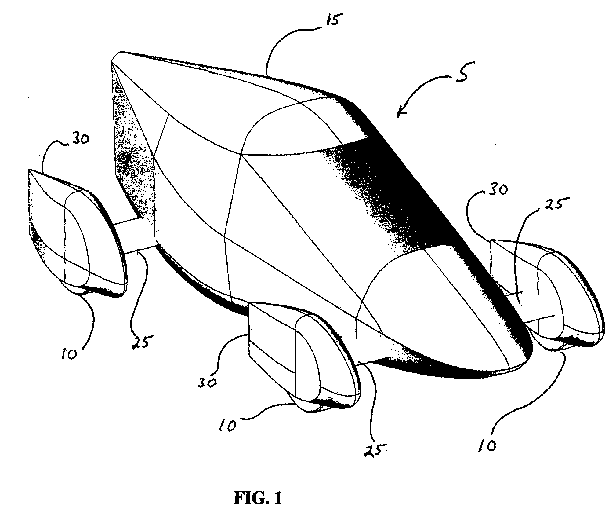
[0043]FIG. 1 provides a perspective view of the exterior of a vehicle 5 employing the suspension system of this invention. Tires 10 are positioned outboard from the vehicle's main body structure 15. Each tire 10 is mounted on a wheel 20 which is not visible in FIG. 1. In the novel system of this invention all moving suspension components are positioned close to or inside of an actual wheel 20. The moving components are, in turn, attached to the vehicle's main structure 15 with a rigid, relatively inflexible transverse beam 25, the shape of which may be straight or assume another configuration, as desired. Each tire 10 and wheel 20 assembly is surrounded by a cowling 30 of minimized cross section to facilitate air flow and thereby reduce aerodynamic drag.

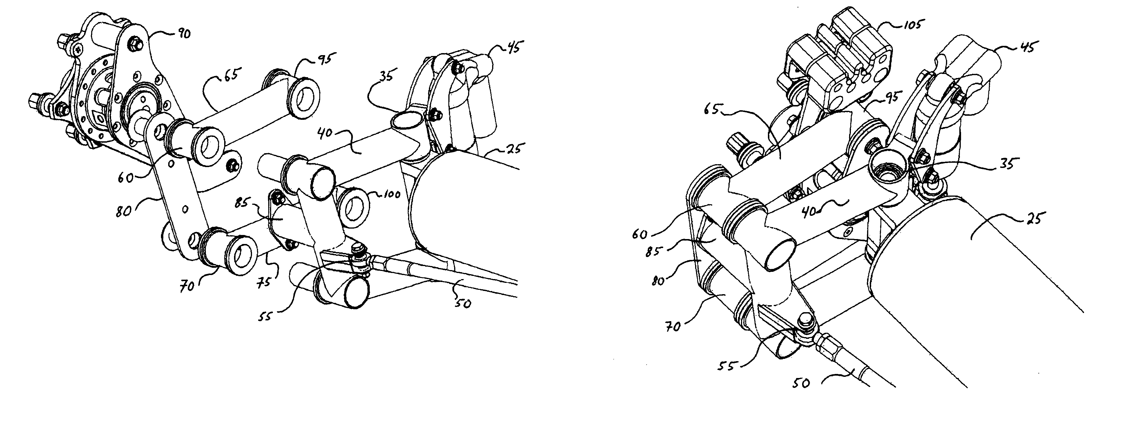
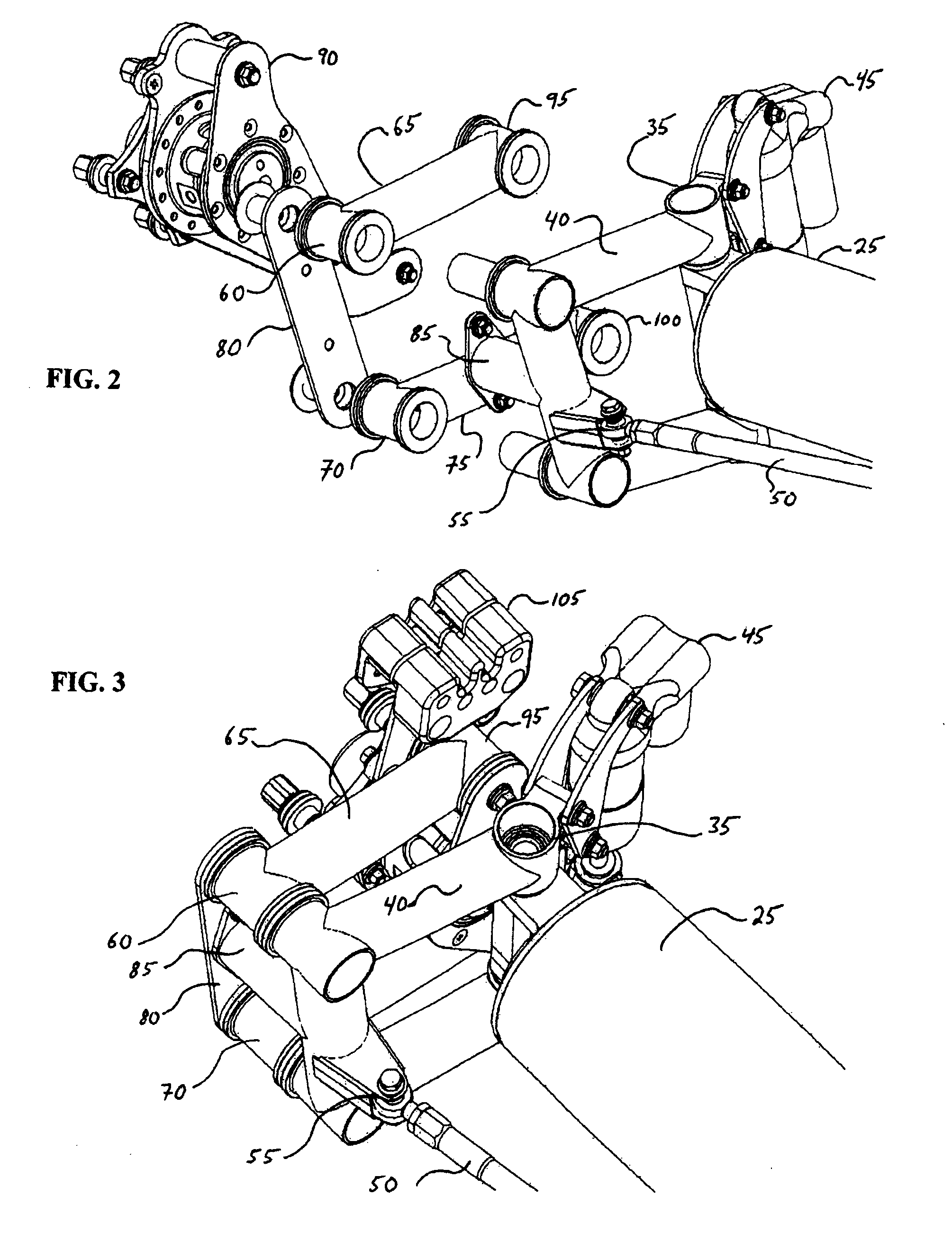
[0044]FIG. 2 prese...


PUM


Abstract

A structurally efficient vehicle suspension system capable of being isolated from the main vehicle structure by being housed within a vehicle's wheel thereby reducing risks of injury during a crash and permitting advantageous redesign of suspension geometry. In the primary embodiment of this invention, the essentially longitudinal links providing wheel travel are outboard of the steering. The upper and / or lower suspension links may be arranged so as to form either a solid triangular-like structure or a “wishbone” form having two separate arms. In addition, the spring / damper unit of the suspension can be configured in a number of different embodiments variously using telescopic dampers, coil springs, rotary dampers, rubber springs, air springs, torsion bars, bell cranks linked to pushrods or pullrods and leaf springs. The spring / damper unit may also be housed in an appropriately enlarged kingpin axis carrier.

Description

CROSS-REFERENCES TO RELATED APPLICATIONS[0001]This application is a continuation-in-part of U.S. Ser. No. 12 / 765,567, filed on Apr. 22, 2010, now U.S. Pat. No. 8,152,184 which is incorporated herein by reference in its entirety.TECHNICAL FIELD[0002]The subject invention relates generally to the field of suspension systems for automotive vehicles. More specifically, the system positions all of the moving parts of a suspension system either inside of or immediately adjacent to each wheel of the vehicle enabling advantageous reshaping of the vehicle.BACKGROUND OF THE INVENTION[0003]Known conventional suspension systems often suffer from one or more problems that individually and / or collectively restrict the design, utility, economy and safety of the vehicles in which they are used. There are many designs which can be considered “conventional” suspension systems, but there are five principal variations.[0004]The first is the Wishbone design which consists of multiple predominantly trans...

Claims


Application Information

Patent Timeline
Patent Type & Authority Patents(United States)
IPC IPC(8): B60G3/02B60G3/20
CPCB60G3/20B60G2204/30B60G2200/18
Inventor MATHIS, RONALD CHRISTOPHERJAEGER, BRADLEY W
Owner EDISON2
Why Eureka
Try Eureka